A bridge vertical reinforcement tensioning equipment

A vertical reinforcement and tensioning technology, applied in bridge construction, bridges, erection/assembly of bridges, etc., can solve problems such as large differences in vertical prestressing design, inability to consider reinforcement deformation, and irregular tensioning process. , to achieve the effect of shortening the construction period, improving the tensioning efficiency, and easy to master

Active Publication Date: 2018-10-30
贵州顺康检测股份有限公司
View PDF6 Cites 0 Cited by
  • Summary
  • Abstract
  • Description
  • Claims
  • Application Information

AI Technical Summary

Problems solved by technology

[0002] Vertical prestressed steel bar is a prestressed system applied to continuous beams with variable cross-section and continuous rigid frame bridges. Its function is to resist the shear stress in the main beam and enhance the rigidity of the structure. Whether the tension is standardized and whether the tension is up to standard has a great impact on the structure. At present, the tension of vertical prestressed steel bars is mainly done manually, using simple mechanical devices to stretch them. The process of tensioning is time-consuming and laborious, and often The pulling process is not standardized, and the force value is not up to standard, resulting in a large difference between the vertical prestress in the beam body and the design, and the loss of vertical prestress is too much
For the application of prestress, a certain operation process is often required, such as stretching to 70% of the prestress value in the first stage, and then stretching again after holding the load for more than 10 minutes. The prestressed tendon can be anchored only after it is deformed or slides stably. The artificial stretching method is generally to pull and anchor immediately, which cannot consider the deformation of the steel bar, which is one of the reasons for the large loss of vertical prestress.

Method used


Image

  • A bridge vertical reinforcement tensioning equipment
  • A bridge vertical reinforcement tensioning equipment
  • A bridge vertical reinforcement tensioning equipment

Examples


Embodiment Construction

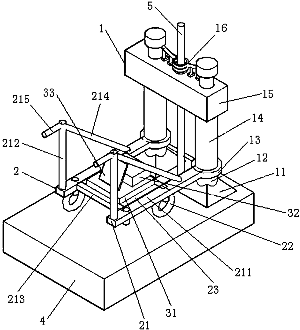
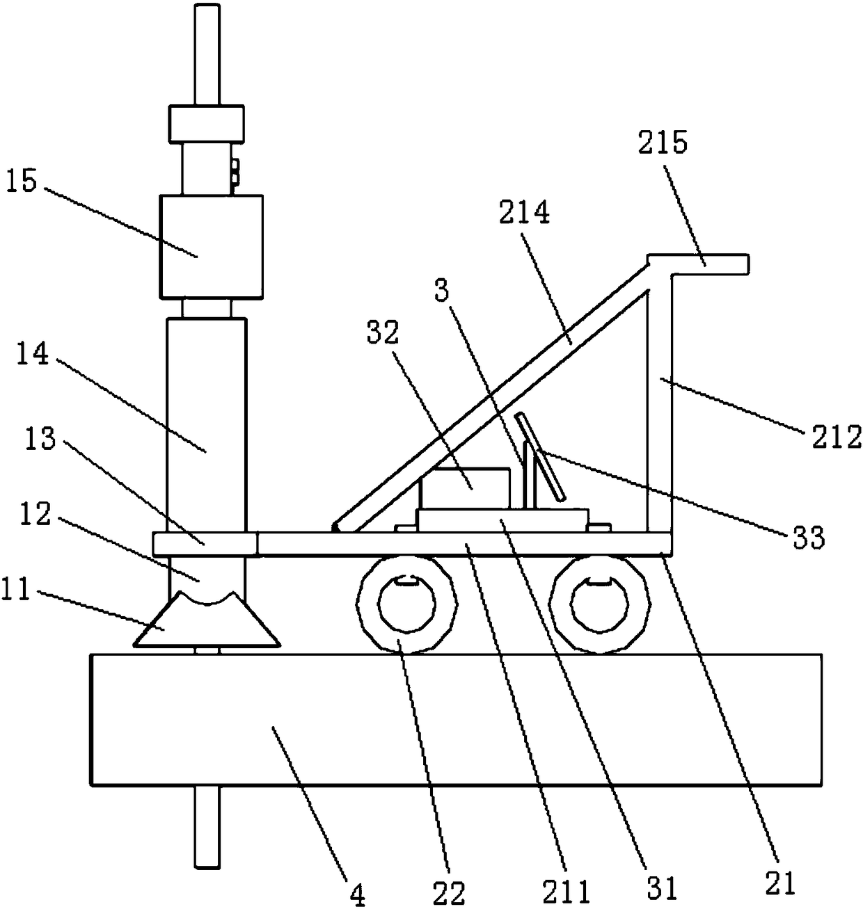
[0017] Such as Figures 1 to 3 As shown, the bridge vertical reinforcement tensioning equipment of the present invention includes a tensioning device 1, a traveling device 2, an energy source and a hydraulic device 3.

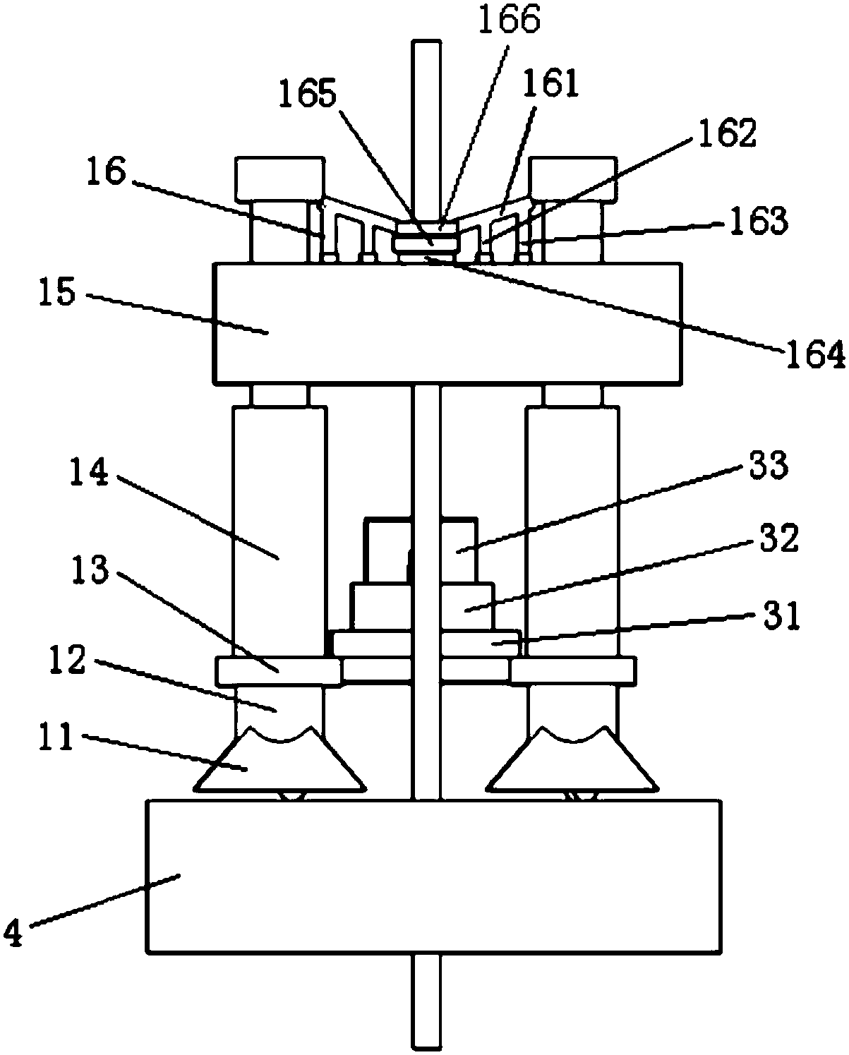
[0018] The tensioning device 1 is arranged on the bridge top plate 4 and includes a support base 11 , a support hydraulic rod 12 , a hydraulic rod support plate 13 , a tension hydraulic rod 14 , a tension platform 15 and a steel lever assembly 16 .

[0019] The support base 11 is a pair arranged along the width direction of the top surface of the bridge top plate 4; or bolted to the top of the support base 11; the hydraulic rod support disc 13 also has a pair, and the bottoms of the pair of hydraulic rod support discs 13 are all connected to the upper ends of a pair of support hydraulic rods 12 by welding or bolts; Rod 14 is a pair of vertical setting, and the bottom end of this pair of tensioning hydraulic rod 14 is connected to the top surface of a pair of h...


PUM


Abstract

The invention relates to stretching equipment for bridge vertical rebar. The stretching equipment comprises a stretching device, a walking device and a power and hydraulic device. The stretching device is installed on a bridge top plate and comprises a pair of support bases, a support hydraulic rod, a hydraulic-rod support disk, a stretch hydraulic rod, a stretching platform and a steel lever component, wherein the pair of support bases are disposed in the width direction of the bridge top-plate top surface, the support hydraulic rod is vertically fixed on the top of the support bases, the hydraulic-rod support disk is vertically fixed on the upper end of the support hydraulic rod, the stretch hydraulic rod is vertically fixed on the top of the hydraulic-rod support disk, the stretching platform is installed in the middle portion of the stretch hydraulic rod, and the steel lever component is disposed on the stretching platform. The walking device is disposed on the bridge top plate and at one side of the walking device, and comprises a walking frame, universal wheels and a plate. The power and hydraulic device is mounted on the walking device and comprises a hydraulic device, a storage battery and a display. The stretching equipment for the bridge vertical rebar has the advantages of convenient operation, good controllability and high stretching efficiency, and can achieve mechanical stretching of the vertical rebar, replace manual labor, guarantee tension prestress quality, thereby saving construction cost.

Description

technical field [0001] The invention belongs to the technical field of bridge construction, and in particular relates to a bridge vertical reinforcement tensioning device. Background technique [0002] Vertical prestressed steel bar is a prestressed system applied to continuous beams with variable cross-section and continuous rigid frame bridges. Its function is to resist the shear stress in the main beam and enhance the rigidity of the structure. Whether the tension is standardized and whether the tension is up to standard has a great impact on the structure. At present, the tension of vertical prestressed steel bars is mainly done manually, using simple mechanical devices to stretch them. The process of tensioning is time-consuming and laborious, and often The pulling process is not standardized, and the force value is not up to standard, resulting in that the vertical prestress in the beam body is often quite different from the design, and the vertical prestress loss is t...

Claims


Application Information

Patent Timeline
Patent Type & Authority Patents(China)
IPC IPC(8): E01D21/00
CPCE01D21/00
Inventor 王涛吴谦杜斌张兴张玉涛车小林沈明轩
Owner 贵州顺康检测股份有限公司
Why Eureka
Try Eureka