High-precision well track monitoring method

A wellbore trajectory and high-precision technology, applied in construction and other fields, can solve problems such as inaccurate calculation results, affecting the accuracy of wellbore trajectory monitoring, errors, etc., to eliminate errors, solve large errors, and improve accuracy and reliability. Effect

Active Publication Date: 2017-07-28
CHINA PETROLEUM & CHEM CORP +1
View PDF4 Cites 10 Cited by
  • Summary
  • Abstract
  • Description
  • Claims
  • Application Information

AI Technical Summary

Problems solved by technology

However, in actual work, this coordinate system conversion problem is often ignored and calculations such as wellbore anti-collision are performed directly, resulting in inaccurate calculation results
[0007] (2) Meridian convergence angle and magnetic declination
Clearly, this simple approach introduces errors
[0009] (3) Map projection problem
[0011] Therefore, due to problems such as map projection deformation and magnetic declination being regarded as a constant in the existing technology, errors will inevitably occur, thereby affecting the monitoring accuracy of the borehole trajectory

Method used


Image

  • High-precision well track monitoring method
  • High-precision well track monitoring method
  • High-precision well track monitoring method

Examples


Embodiment 1

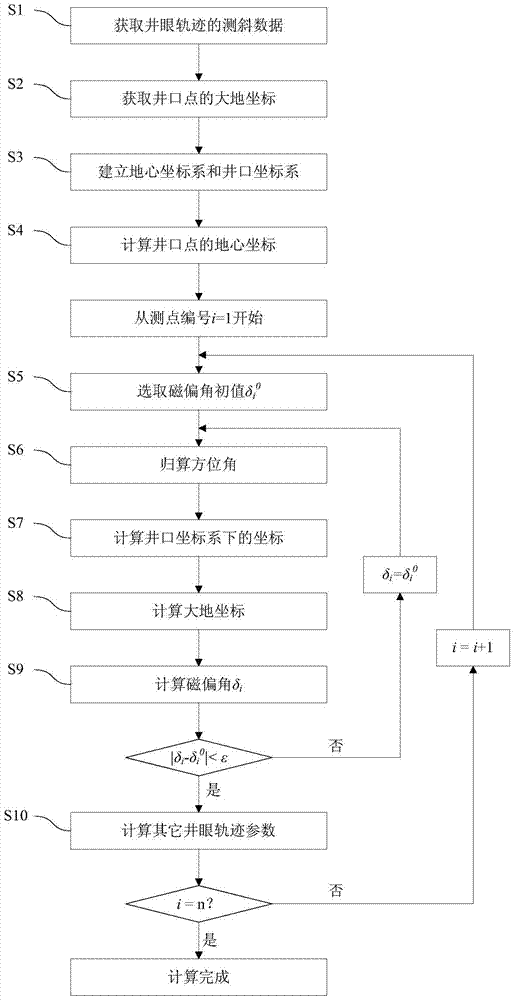
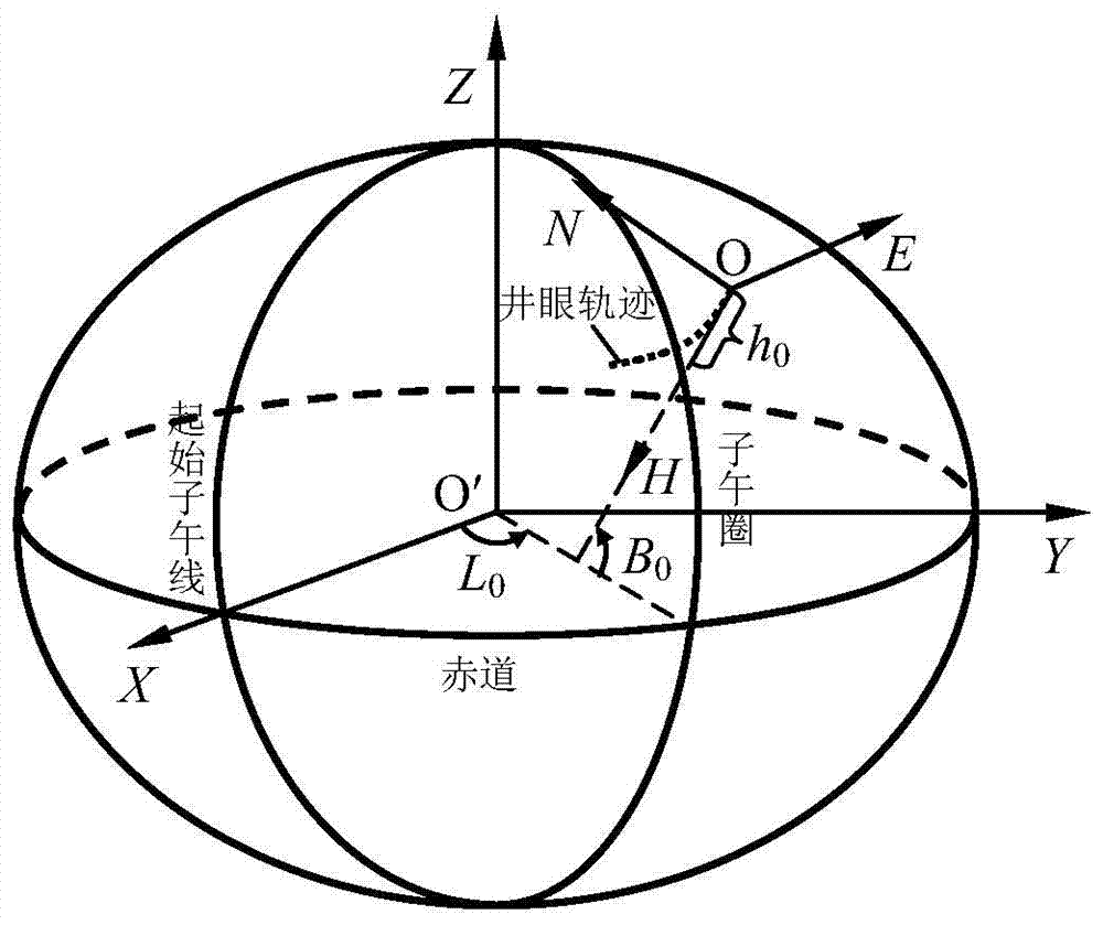
[0049] The basic task of borehole trajectory monitoring is to obtain the spatial coordinates of each measuring point. For this reason, a spatial Cartesian coordinate system O-NEH, referred to as the wellhead coordinate system, is established at the wellhead. For the first measurement point, it can be considered as a measurement section with the wellhead point. The wellhead point is not the actual measuring point, it can be marked with i=0 for convenience. Since all the parameters of the wellhead point are known data, the spatial coordinates of the first measuring point can be obtained as long as the coordinate increment in the measuring section is calculated. The calculation results of the actual drilled wellbore trajectory can be obtained by analogy of the measured section by section. Therefore, the real drilling trajectory monitoring problem can be attributed to the following proposition: on the real drilling trajectory, the inclination data of two adjacent measuring point...

Embodiment 2

[0094] This embodiment is an example of monitoring a horizontal well by using the wellbore trajectory monitoring method provided in the above embodiments.

[0095] The geodetic coordinates of the wellhead point of the horizontal well is the geodetic longitude L 0 =85°20′E, geodetic latitude B 0 =38°50′N, elevation h 0 = 1000.00m, the date of drilling is August 12, 2016. Adopt the natural curve model of wellbore trajectory and the International Geomagnetic Reference Field (IGRF-12) model, see Table 1 and Table 2 for the actual drilling wellbore trajectory calculated by the inclination data according to the prior art and the method of the present invention.

[0096] Table 1. Wellbore trajectory monitoring results of the prior art

[0097]

[0098] Table 2 Borehole trajectory monitoring results of the embodiment of the present invention

[0099]

[0100]

[0101] The results show that the vertical depth and horizontal length of each measuring point calculated by the ...


PUM


Abstract

The invention discloses a high-precision well track monitoring method. The high-precision well track monitoring method comprises the steps of calculation of geocentric coordinates of a wellhead point, selection of the initial value of a magnetic declination, azimuth angle conversion, calculation of coordinates under a wellhead coordinate system, geodetic coordinate calculation, magnetic declination calculation, magnetic declination precision verification, calculation of other track parameters and the like. According to the high-precision well track monitoring method, changes of the magnetic declination along a well track are considered, the parameters such as the magnetic declinations, the true azimuth angles and the space coordinates of all measuring points are sequentially determined through an iteration method, and therefore the precision and reliability of well track monitoring are remarkably improved.

Description

technical field [0001] The invention relates to the technical field of oil and gas drilling, in particular to a high-precision wellbore trajectory monitoring method. Background technique [0002] Drilling engineers often use the wellhead coordinate system to design, monitor and control the wellbore trajectory, while geoscientists use the geodetic coordinate system to describe the earth structure and reservoir distribution. To adapt and meet the needs of oil and gas exploration and development, the problem of wellbore positioning must be solved. [0003] The existing technology is based on the principle of map projection to reduce the wellbore trajectory. In this method, the wellbore trajectory is designed according to the map projection coordinates of the wellhead and the target point, and the north direction is the coordinate north of the map projection plane. Since map projection and projection transformation are involved, and the measured azimuth is mostly magnetic azim...

Claims


Application Information

Patent Timeline
Patent Type & Authority Applications(China)
IPC IPC(8): E21B47/0228
CPCE21B47/0228
Inventor 刘修善
Owner CHINA PETROLEUM & CHEM CORP
Why Eureka
Try Eureka