Condensation type secondary heat exchanger

A heat exchanger, condensing technology, applied in the field of heat exchange, can solve the problems of poor heat exchange effect, high manufacturing cost, hot water pipe falling off, etc., to reduce heat loss, avoid secondary evaporation, and improve heat exchange efficiency Effect

Pending Publication Date: 2017-07-28
ZHEJIANG GUANGTAO HEALTHY KITCHEN UTENSILS CO LTD
View PDF10 Cites 7 Cited by
  • Summary
  • Abstract
  • Description
  • Claims
  • Application Information

AI Technical Summary

Problems solved by technology

[0004] The above-mentioned structure has the following problems: the high-temperature heat exchanger and the condensing heat exchanger are designed in a split structure, and the flue gas from the high-temperature heat exchanger needs to be driven by a fan to enter the condensing heat exchanger, which is not only complicated in structure, but also The manufacturing cost is high; in the condensing heat exchanger, the flow direction of the flue gas is the same as that of a part of the cold water, which fails to achieve the purpose of condensing heat exchange, and the heat exchange effect is poor; the outlet section of the hot water pipe is directly coiled around the high temperature heat exchanger On the shell, the connection stability between the shell and the shell is poor, and it is very easy for the hot water pipe to fall off. The hot water pipe must be in a spiral shape to be coiled on the high-temperature water heater. The spiral hot water pipe is not easy to manufacture, and the manufacturing cost high

Method used


Image

  • Condensation type secondary heat exchanger
  • Condensation type secondary heat exchanger
  • Condensation type secondary heat exchanger

Examples


Embodiment 1

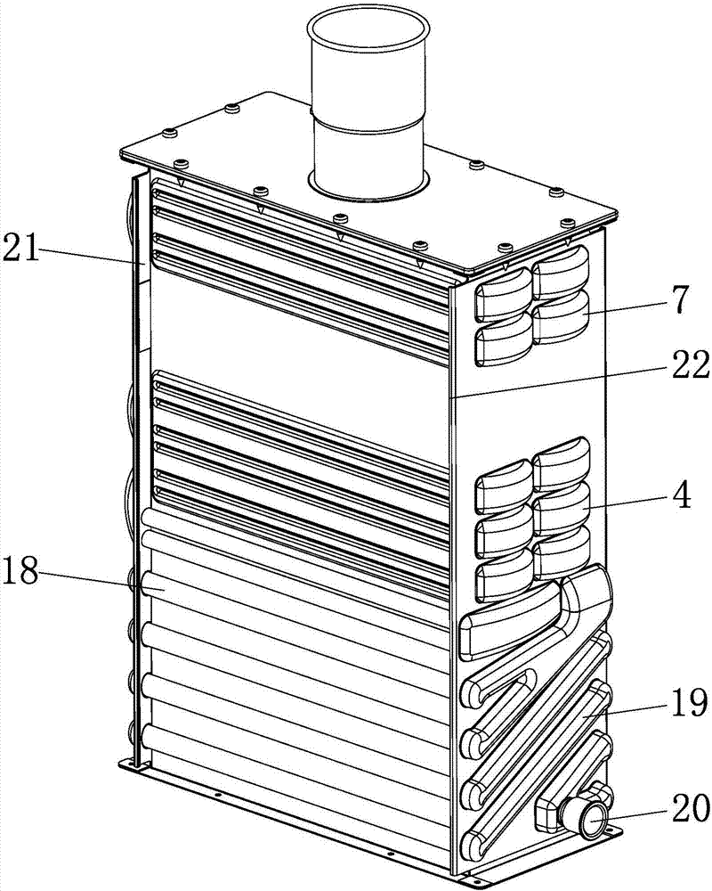
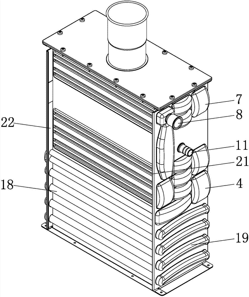
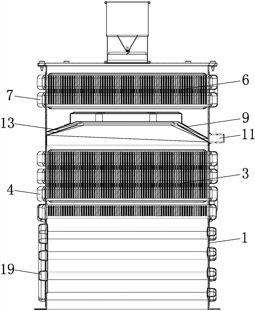
[0033] Such as figure 1 and figure 2The shown condensing secondary heat exchanger includes a cylindrical shell 1, and the interior of the shell 1 has a vertically arranged flue gas channel, such as image 3 with 4 As shown, the middle part of the flue gas passage is transversely provided with a number of parallel heat exchange tubes-2 and a heat absorber-3 sleeved on the number of heat exchange tubes-2, and the two ends of the number of heat exchange tubes-2 are respectively connected to the The outer wall of the housing 1 is flush, such as figure 1 with figure 2 As shown, the outer wall of the housing 1 has several water box covers 4 for connecting several heat exchange tubes 2 in series to form a series waterway 1, and the upper part of the flue gas channel is provided with a condensed water heat exchange structure, and the condensed water structure The outlet of the outlet is connected with the inlet of the series waterway one, and the flue gas channel is also provide...

Embodiment 2

[0048] The structural principle of this embodiment is basically the same as that of Embodiment 1, the difference is that, as Image 6 with Figure 7 As shown, several heat exchange tubes surrounding the shell are arranged in parallel, that is, enter from the water inlet joint 8, then surround the shell surface in two ways, and finally connect together in parallel and discharge from the water outlet joint 20.


PUM


Abstract

The invention provides a condensation type secondary heat exchanger, belongs to the technical field of heat exchange, and solves the problems that the conventional condensation type secondary heat exchanger is incompact in structure and poor in the heat exchanging effect; the condensation type secondary heat exchanger comprises a cylindrical housing, wherein a flue gas channel is vertically arranged in the housing; a plurality of parallel heat exchange tubes 1 and a heat absorbing body 1 sleeving the plurality of parallel heat exchange tubes 1 are transversely arranged at the middle of the flue gas channel in a penetrating manner; the two ends of each of the plurality of heat exchange tubes 1 are flush with the outer wall of the housing; a plurality of water chamber covers 1 used for connecting the plurality of heat exchange tubes 1 in series to form a series connection water circuit 1 are arranged on the outer wall of the housing; a condensate water heat exchange structure is arranged at the upper part of the flue gas channel; the outlet of the condensate water heat exchange structure is communicated with the inlet of the series connection water circuit 1; a condensate water recovery structure used for preventing the condensate water of the condensate water heat exchange structure from falling into the heat absorbing body 1 is further arranged in the flue gas channel. The condensation type secondary heat exchanger has the advantages that the structure is compact and the heat exchanging effect is good.

Description

technical field [0001] The invention belongs to the technical field of heat exchange, and relates to a heat exchanger of a gas water heater, in particular to a condensing secondary heat exchanger. Background technique [0002] A gas water heater refers to a gas appliance that uses gas as a fuel to transfer heat to cold water flowing through a heat exchanger through combustion heating to achieve the purpose of preparing hot water. Traditional gas water heaters include combustion chambers, heat exchangers and other devices. The heat exchanger absorbs the energy generated by burning gas and transfers it to the cold water flowing through the heat exchanger through the water inlet pipe. After heat exchange, the water temperature rises and the heat The water is discharged from the outlet pipe to realize the function of heating the water flow, while the high-temperature flue gas generated by the combustion is discharged by the fan through the pipe chamber. More than 10% of the hea...

Claims


Application Information

Patent Timeline
Patent Type & Authority Applications(China)
IPC IPC(8): F24H8/00F28D7/08F28B1/02F28D21/00
CPCF24H8/00F28B1/02F28D7/08F28D21/0007Y02B30/00
Inventor 陈玲辉
Owner ZHEJIANG GUANGTAO HEALTHY KITCHEN UTENSILS CO LTD
Why Eureka
Try Eureka