Technique and device for detecting sub-aperture stitching of large aperture plane optical element

A technology of sub-aperture splicing and optical components, applied in the direction of using optical devices, measuring devices, instruments, etc., can solve the problems of large-size displays, difficult to guarantee reset accuracy, surface interference after stripes, etc., to achieve environmental disturbance suppression, low cost, resistance to Good vibrating ability

Inactive Publication Date: 2017-07-28
SICHUAN UNIV
View PDF7 Cites 13 Cited by
  • Summary
  • Abstract
  • Description
  • Claims
  • Application Information

AI Technical Summary

Problems solved by technology

In view of the disadvantages of traditional phase measurement deflection surgery that require a large-size display, reset accuracy is difficult to guarantee, and the collected fringes are susceptible to rear surface interference, by in

Method used


Image

  • Technique and device for detecting sub-aperture stitching of large aperture plane optical element
  • Technique and device for detecting sub-aperture stitching of large aperture plane optical element
  • Technique and device for detecting sub-aperture stitching of large aperture plane optical element

Examples


Embodiment Construction

[0022] The present invention will be described in detail below by examples in conjunction with the accompanying drawings. It is necessary to point out that the following examples are only used for further description of the present invention, and cannot be interpreted as limiting the protection scope of the present invention, and those skilled in the art make some non-essential improvements to the present invention according to the above-mentioned content of the present invention And adjustments still belong to the protection scope of the present invention.

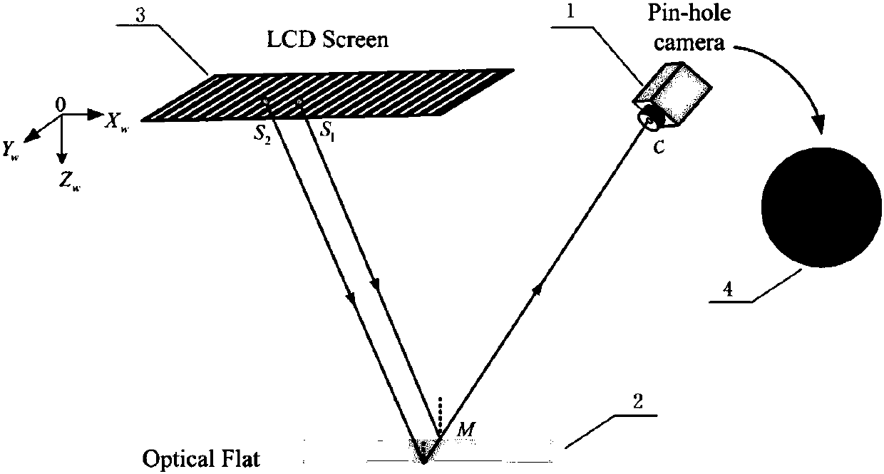
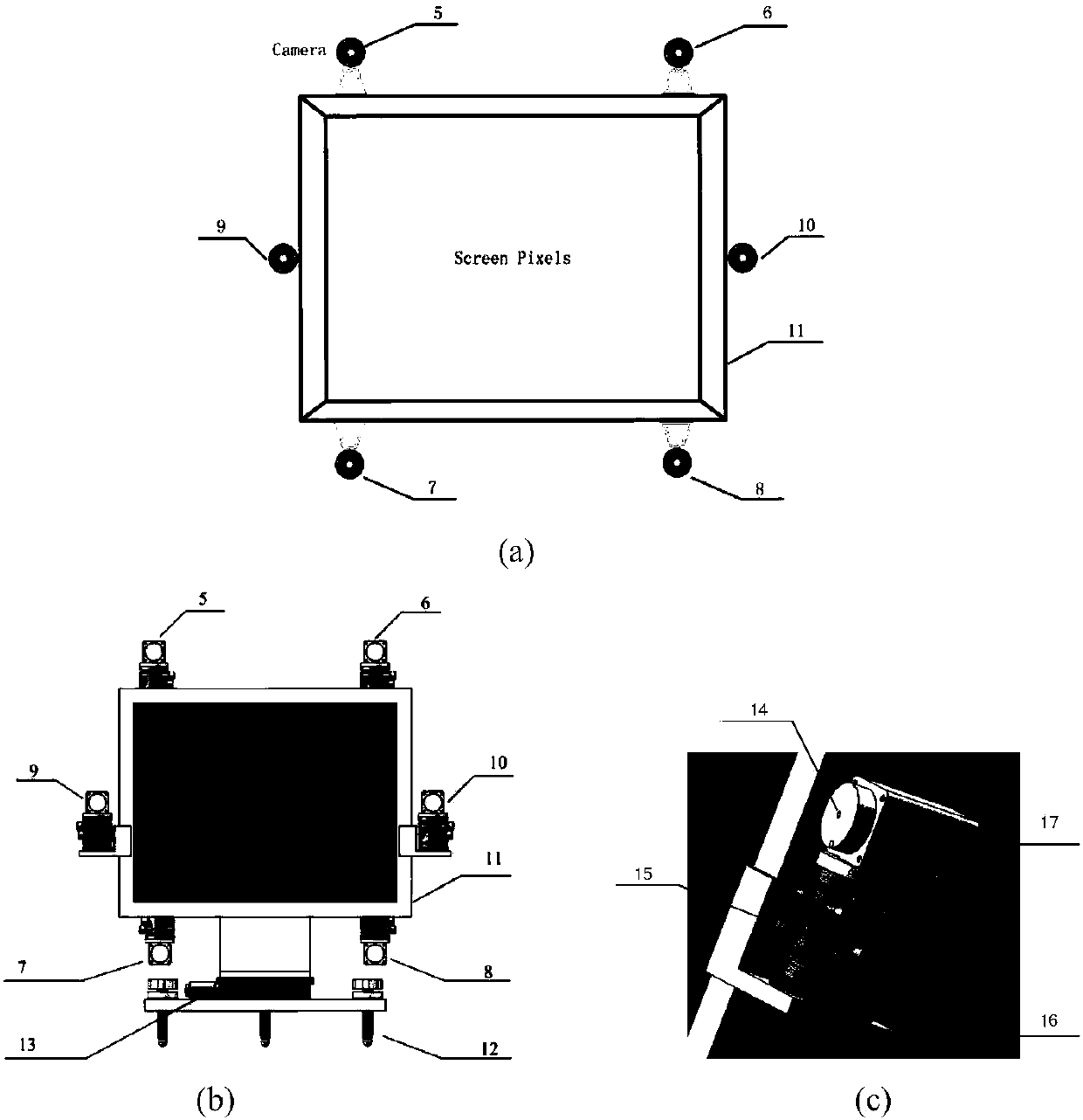
[0023] The present invention includes a plurality of cameras to form an image acquisition system, wherein the principle of phase measurement deflection of one camera is as follows: figure 1 As shown, its basic components include a pinhole camera 1 , a planar optical element 2 , and a display 3 . The sinusoidal coded fringe pattern is displayed on the commercial display 3, and is collected by the pinhole camera 1 after be...


PUM


Abstract

The invention provides a technique and device for detecting the sub-aperture stitching of a large aperture plane optical element. When the technique is used to measure an optical element, basic devices include a plurality of pinhole cameras, a plane optical element, and a display. A series of sinusoidal encoded periodically changed fringe patterns are shown on the display, and are collected simultaneously by the plurality of pinhole cameras after reflection by a measured surface. To avoid the interference of the rear surface reflected light, a spectral estimation algorithm is used to calculate coordinates of the reflected light in the display plane, and a ray tracing for the reference coordinate plane for the reference method is introduced to achieve the precise reset of the reference surface and the measured surface, thus deducting a system error of a test system. Slope data obtained by the plurality of cameras are subjected to a sub-aperture stitching algorithm to obtain the slope distribution on the measured full aperture, and then integration is conducted to obtain the surface profile distribution of the large aperture plane optical element. The designed test device has the advantages of simple structure, good shock resistance and high test precision, which can provide a new idea for the online detection of large aperture plane optical elements.

Description

technical field [0001] The present invention relates to the technical field of phase measuring deflectometry (PMD, Phase Measuring Deflectometry) to detect the surface shape of optical elements, in particular to a technology based on sub-aperture stitching (Sub-aperture Stitching) to realize the surface shape of large-aperture planar optical elements Precise detection of phase measurement deflection. Background technique [0002] Interferometry has been a feasible and commonly used non-contact, high-precision surface detection technology for a century. The main reasons for its wide application are: (1) the height phase mapping relationship in the measurement is simple and direct, (2) because the measured object is measured by the wavelength, it has high measurement accuracy. However, when measuring the surface shape of large-diameter components, the environmental requirements are very harsh. Usually, accurate detection can only be carried out in a controlled laboratory envi...

Claims


Application Information

Patent Timeline
IPC IPC(8): G01B11/24
CPCG01B11/2441
Inventor 李大海鄂可伟王琴章涛
Owner SICHUAN UNIV
Why Eureka
Try Eureka