
Camera and camera anti-shake method

A camera and lens assembly technology, applied in the field of photography, can solve problems such as large structure, high cost, and complex design

Active Publication Date: 2019-10-15
VIVO MOBILE COMM CO LTD
View PDF6 Cites 2 Cited by
  • Summary
  • Abstract
  • Description
  • Claims
  • Application Information

AI Technical Summary

Problems solved by technology

[0004] However, the above-mentioned OIS camera uses voice coil motors, magnets, coils and Hall sensors, etc., the design is complex, the cost is relatively high, and the structure is relatively large

Method used


Image

  • Camera and camera anti-shake method
  • Camera and camera anti-shake method
  • Camera and camera anti-shake method

Examples


Embodiment 1

[0027] see Figure 4 , the present embodiment provides a camera, including a total reflection mirror assembly 10, a lens assembly 20 and a circuit assembly 30; the total reflection mirror assembly 10 includes a total reflection mirror 11 and a first shape memory alloy metal disposed on the total reflection mirror 11 Wire 12, the lens assembly 20 includes a lens, and the circuit assembly 30 includes a tilt detector 31 and a drive chip 32; wherein the tilt detector 31 is used to detect the shaking parameters of the total reflection mirror 11 shaking, and convert the shaking parameters into a first electrical signal To transmit; the drive chip 32 is used to receive the first electrical signal, calculate the compensation displacement according to the first electrical signal, and output the first current to the first shape memory alloy wire 12 after calculation; the first shape memory alloy wire 12 is used to generate the first pulling force under the action of the first current to...

Embodiment 2

[0059] see Figure 12 , this embodiment provides a camera anti-shake method, the anti-shake method is suitable for the camera in the first embodiment, the anti-shake method includes:

[0060] Step S1: Detect the shaking parameters of the shaking of the total reflection mirror 11, and convert the shaking parameters into a first electrical signal for transmission.

[0061] Step S2: receiving the first electrical signal, calculating the compensation displacement according to the first electrical signal, obtaining a first current according to the compensation displacement, and outputting the first current to the first shape memory alloy wire.

[0062] Step S3: the first shape memory alloy wire 12 generates a first pulling force under the action of the first current, and pulls the total reflection mirror 11 to perform a position compensation movement.

[0063] When the total reflection mirror 11 shakes, the lens shifts accordingly, so as to reduce the impact caused by the shake. ...


PUM


Abstract

Embodiments of the present invention provide a camera and a method for anti-shake of the camera, which relate to the field of camera technology, so as to reduce the cost of the camera and simplify the structure of the camera. Wherein, the total reflection mirror assembly of the camera includes a total reflection mirror and a first shape memory alloy wire arranged on the total reflection mirror, its lens assembly includes a lens, and its circuit assembly includes a tilt detector and a drive chip; It is used to detect the jitter parameters of the total reflection mirror jitter, and convert the jitter parameters into the first electrical signal for transmission; the driver chip is used to receive the first electrical signal, and calculate the compensation displacement according to the first electrical signal, and after the calculation The first shape memory alloy wire outputs a first current; the first shape memory alloy wire is used to generate a first pulling force under the action of the first current, and pull the total reflection mirror to move to the compensation position.

Description

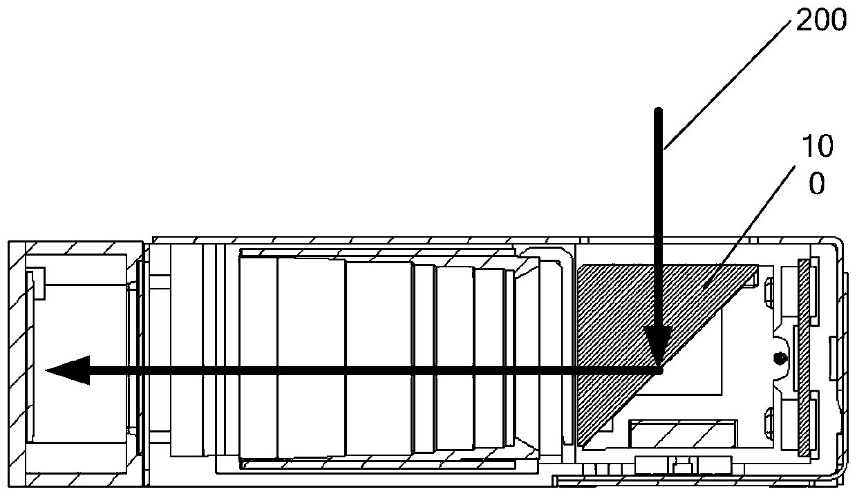
technical field [0001] The invention relates to the technical field of photography, in particular to a camera and a camera anti-shake method. Background technique [0002] A periscope optical zoom (Optical Image Stabilization, referred to as OIS) camera is a camera that uses optical zoom technology to shoot. It has the characteristics of changing the focal length and keeping the size of the image plane. figure 1 , the OIS camera uses a total reflection prism 100 to turn the light 200 degrees to 90 degrees before entering the lens, changing the original front and rear adjustment focal length into left and right adjustment, reducing the storage space of the camera device in the thickness direction, and realizing the ultra-high performance of the camera device thinning. [0003] The common OIS camera has anti-shake function to improve the shooting quality. The OIS camera is equipped with a voice coil motor, a magnet, a coil and a Hall sensor. The voice coil motor energizes th...

Claims


Application Information

Patent Timeline
Patent Type & Authority Patents(China)
IPC IPC(8): G02B27/64G03B5/00H04N5/232
CPCG02B27/642G02B27/646G03B5/00H04N23/685
Inventor 杨卓坚李文珍杨尚明庞钦全
Owner VIVO MOBILE COMM CO LTD
Learn More