
Detection method and device

A detection method and road surface detection technology, which is applied in the field of image processing, can solve problems such as insufficient robustness of road detection algorithms, and achieve the effect of solving roadside shadow problems

Inactive Publication Date: 2017-07-28
FOSHAN NANHAI GUANGDONG TECH UNIV CNC EQUIP COOP INNOVATION INST +1
View PDF0 Cites 6 Cited by
  • Summary
  • Abstract
  • Description
  • Claims
  • Application Information

AI Technical Summary

Problems solved by technology

In the process of road surface detection, the most common interference is shadows. In order to solve the influence of shadows on road surface detection results, the current traditional road surface detection algorithms still cannot solve this problem well, so the road detection algorithms in complex environments are still robust. Sex is not enough

Method used


Image

  • Detection method and device
  • Detection method and device
  • Detection method and device

Examples


Embodiment 1

[0070] Embodiment 1: a kind of detection method.

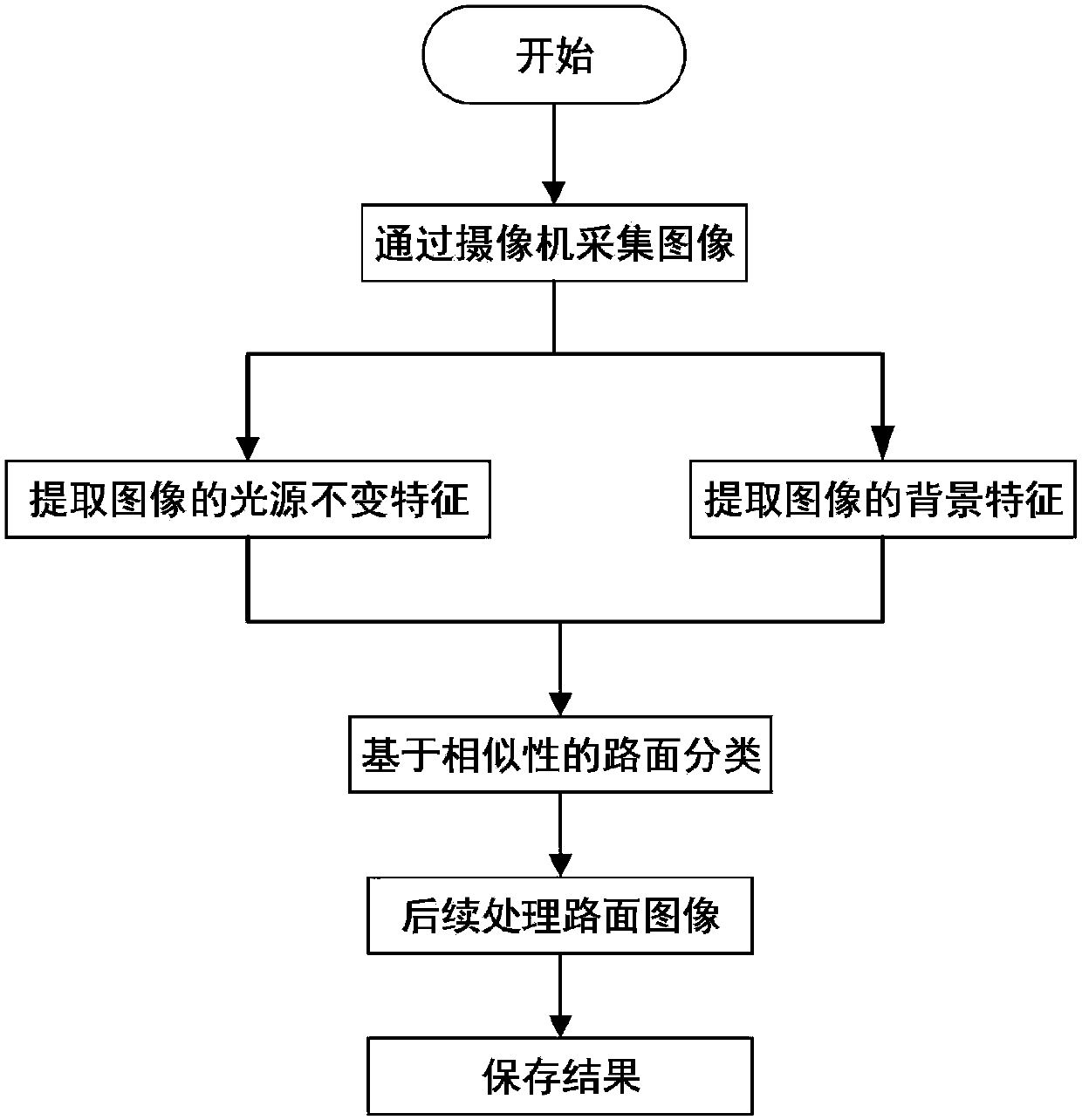
[0071] refer to Figure 1 to Figure 5 As shown, a detection method specifically includes the following steps:

[0072] S1. Collect images through the on-board camera: position the camera directly in front of the vehicle, so that the information of the left and right lanes of the road ahead and the information of the feasible area of ​​the road can be completely captured;

[0073] S2. Extracting the light source invariant features of the image: extracting the light source invariant features of the image mainly includes three steps:

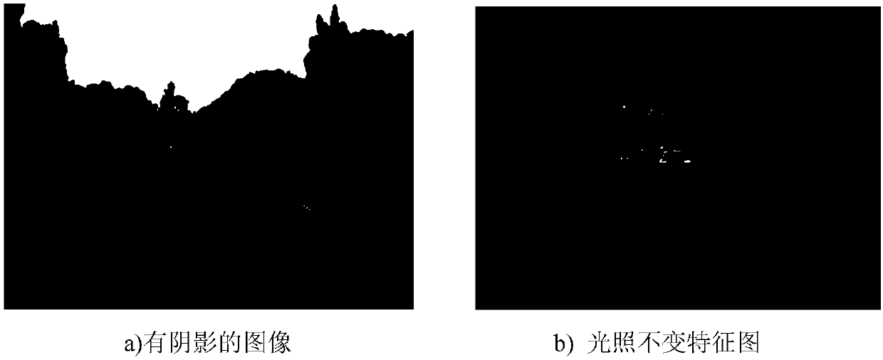
[0074] S21, the RGB image I collected by step S1 RGB Calculate a light-invariant feature map I with reduced brightness influence, that is, a large amount of shadow attenuation, the effect is shown in Figure 2;

[0075] S22. Preliminarily extract the road surface area based on area growth based on the invariant characteristics of the light source;

[0076] S23. Calculate the light source invaria...

Embodiment 2

[0123] Embodiment 2: a detection device.

[0124] A detection device based on the detection method in embodiment 1, comprising:

[0125]Image acquisition module: use the CCD camera to capture the video image of the road surface, and transmit the data to the image processing module;

[0126] Wherein, the image acquisition module also includes: the CCD camera is positioned directly in front of the vehicle to completely capture the feasible area of ​​the road surface, and transmit the image to the image processing module.

[0127] Image processing module: perform image processing on image data to obtain road surface detection results;

[0128] Among them, FPGA is equipped with image processing algorithm, which mainly extracts the light source invariant features of the image, extracts the background features of the image, and classifies the road surface based on similarity according to the light source invariant feature and background feature of the image, and sends the final det...


PUM


Abstract

A detection method provided by the present invention comprises the steps of acquiring an image via a vehicle-mounted camera; extracting the light source invariant features of the image; extracting the background features of the image; according to the light source constant features and the background features of the image, carrying out the pavement classification based on the similarity; and finally carrying out the subsequent processing based on the communicated areas on the pavement images, etc. By extracting the illumination invariant features of the image, a detection failure problem caused by a roadside shadow problem is solved. The video or image sequence changes continuously along with the time, and the pavement also has certain continuity about a time axis, so that the corresponding relation between the front and back two frames of images can be established. During a positioning process of the pavement pixels, by utilizing the detection result of the previous frame of image to extract the background features of the image, the detection speed and the detection accuracy are improved, so that the detection method has the strong robustness and satisfies the real-time requirements of the practical application.

Description

technical field [0001] The invention relates to the technical field of image processing, in particular to a detection method and device. Background technique [0002] In the past decade, assisted driving systems and self-driving cars have made significant progress in protecting road safety by monitoring the road environment. Especially, pavement inspection technology has become a hot topic worldwide because of its significance. A variety of sensor technologies are used in this field, mainly including radar, laser and machine vision. At the same time, image processing technology has achieved rapid development in recent years. On the one hand, cameras are cheaper, smaller, and have better quality than before. On the other hand, the computing power of computers is also increasing day by day. In recent years, image processing units for parallel computing have also appeared. With the development of hardware, machine vision has become an application technology that can meet the ...

Claims


Application Information

Patent Timeline
IPC IPC(8): G06K9/00G06K9/20G06K9/34G06K9/62
CPCG06V20/56G06V10/235G06V10/267G06F18/22G06F18/24
Inventor 黄坤山
Owner FOSHAN NANHAI GUANGDONG TECH UNIV CNC EQUIP COOP INNOVATION INST
Learn More