Light emitting control drive circuit, display device and drive method

A light-emitting drive and circuit technology, applied in static indicators, instruments, etc., can solve the problems of abnormal display of pixel units and unstable voltage.

Active Publication Date: 2017-07-28
BOE TECH GRP CO LTD
View PDF10 Cites 6 Cited by
  • Summary
  • Abstract
  • Description
  • Claims
  • Application Information

AI Technical Summary

Problems solved by technology

[0003] Embodiments of the present invention provide a control light-emitting driving circuit, a display device, and a driving method to solve the problem in the prior art tha

Method used


Image

  • Light emitting control drive circuit, display device and drive method
  • Light emitting control drive circuit, display device and drive method
  • Light emitting control drive circuit, display device and drive method

Examples


Embodiment Construction

[0026] The following will clearly and completely describe the technical solutions in the embodiments of the present invention with reference to the accompanying drawings in the embodiments of the present invention. Obviously, the described embodiments are some of the embodiments of the present invention, but not all of them. Based on the embodiments of the present invention, all other embodiments obtained by persons of ordinary skill in the art without creative efforts fall within the protection scope of the present invention.

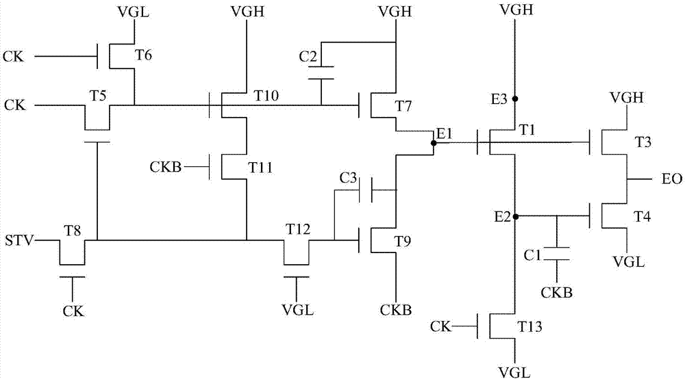
[0027] The inventor based on figure 1 According to the circuit structure of the control light-emitting drive circuit in the prior art, it is found that in the light-emitting stage, since the first transistor T1 is connected to the first level signal input terminal VGH, in the light-emitting stage, when the first level signal input terminal VGH is input to the second In case of a one-level signal, the seventh transistor T7 outputs the first-level signal...


PUM


Abstract

Embodiments of the invention provide a light emitting control drive circuit, a display device and a drive method. The light emitting control circuit is used for controlling switching on and off of a pixel unit and comprises a first control module, a first output module, a second control module, a second output module, a third control module and a fourth control module. When the first control module outputs a first level signal to a first control node, the first output module is switched off, and the second output module is switched on. When a first clock signal input in a first clock signal input end is a switching on signal, the fourth control module is switched on and reduces voltage of the first level signal input in the first level signal input end, and outputs the first level signal of reduced voltage to a third control node, so that the voltage value of the first control node is larger than or equal to the voltage value of the third control node, and the third control module is maintained switched off. Therefore, the problem that the display is abnormal due to multi-line output of signal output nodes of the pixel unit in the light emitting stage is solved.

Description

technical field [0001] The present invention relates to the technical field of controlling light-emitting driving circuits, in particular to a controlling light-emitting driving circuit, a display device and a driving method. Background technique [0002] AMOLED (Active-matrix organic light emitting diode, active-matrix organic light-emitting diode) display device, in addition to OLED organic light-emitting devices, the main components of the drive backplane circuit are gate drive circuit, reset drive circuit and control light-emitting drive circuit. The gate drive circuit and the reset drive circuit are shift registers that provide voltage for the light-emitting preparation stage (non-light-emitting). The control light-emitting drive circuit is a shift register that controls light-emitting time and timing. like figure 1 As shown, the light emitting control driving circuit is composed of a first transistor T1, a third transistor T3 to a thirteenth transistor T13, and a fir...

Claims


Application Information

Patent Timeline
IPC IPC(8): G09G3/3225
CPCG09G3/3225G09G3/3266G09G2310/0286G09G3/3258G09G2300/0842
Inventor 玄明花杨盛际卢鹏程付杰王磊肖丽
Owner BOE TECH GRP CO LTD
Why Eureka
Try Eureka