Selection method of positions of mura compensation data reference value

A technology for compensating data and reference values, applied to instruments, static indicators, etc., can solve the problem of inability to effectively calculate the compensation data of the light and dark limit positions, and achieve the effect of improving the mura compensation effect and avoiding limitations.

Active Publication Date: 2017-07-28
SHENZHEN CHINA STAR OPTOELECTRONICS TECH CO LTD
View PDF6 Cites 23 Cited by
  • Summary
  • Abstract
  • Description
  • Claims
  • Application Information

AI Technical Summary

Problems solved by technology

image 3 In the lower half of the coordinate system, the vertical axis represents the brightness, and the horizontal axis represents the pixel position perpendicular to the direction of the light-dark boundary. The reference value positions of the compensation data are respectively located on both sides of the light-dark boundary. According to the reference value position and the reference value, the linear interpolation algorithm can be used to obtain The line segment representing the calculation result of linear interpolation is obtained, and the line segment representing the calculation result of linear interpolation is synthesized with the polyline representing the original brightness to obtain the polyline representing the brightness after compensation. By comparing the original brightness and the brightness after compensation at the bright and dark boundary position, it can be known that Existing methods cannot effectively calculate the compensation data for the bright and dark boundary position

Method used


Image

  • Selection method of positions of mura compensation data reference value
  • Selection method of positions of mura compensation data reference value
  • Selection method of positions of mura compensation data reference value

Examples


Embodiment Construction

[0031] See Image 6 , Which is a flowchart of the method for selecting the position of the reference value of the mura compensation data of the present invention. The selection method of the reference value position of the mura compensation data mainly includes:

[0032] Step 10. Use the camera to shoot the original mura state of the grayscale image of the panel;

[0033] The camera of the mura repair equipment can be used to photograph the panel;

[0034] Step 20. When the camera detects the mura extending in the horizontal direction and the corresponding light and dark boundaries extending in the horizontal direction, make the light and dark boundaries within the set horizontal rectangular interval and set the vertex pixels of the horizontal rectangular interval Is the position of the reference value of mura compensation data;

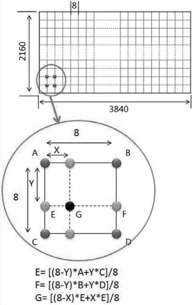
[0035] When there are horizontal band-shaped mura and light-dark boundaries on the panel, a rectangular interval such as 16*4 or 32*2 can be selected as t...


PUM


Abstract

The invention relates to a selection method of positions of a mura compensation data reference value. The selection method comprise steps of step 10, using a camera to shoot the original mura state of a gray scale frame of a panel; step 20, when the camera detects a mura extending in the horizontal direction and a bright and dark boundary extending in the corresponding horizontal direction, allowing the bright and dark boundary to be in a rectangular interval in the set horizontal direction, and setting the top pixel of the rectangular interval in the set horizontal direction to be the position of a mura compensation data reference value; and step 30, when the camera detects a mura extending in the vertical direction and a bright and dark boundary extending in the corresponding vertical direction, allowing the bright and dark boundary to be in a rectangular interval in the set vertical direction, and setting the top pixel of the rectangular interval in the set vertical direction to be the position of the mura compensation data reference value. According to the invention, a mura compensation effect of a bright and dark boundary position can be effectively improved.

Description

Technical field [0001] The invention relates to the field of liquid crystal displays, and in particular to a method for selecting a reference value position of mura compensation data. Background technique [0002] Flat display devices such as liquid crystal displays (LCD) are widely used in mobile phones, TVs, personal digital assistants, digital cameras, notebook computers, and desktop computers due to their high image quality, power saving, thin body and wide application range. Various consumer electronic products have become the mainstream of display devices. [0003] Such as Figure 1A As shown, it is a structural block diagram of an existing uneven brightness compensation device. In order to solve the uneven brightness (mura) caused by defects in the LCD manufacturing process / devices, the existing compensation method for uneven brightness is to store the grayscale compensation data in the flash 11 matched with the panel. Then the timing control chip (TCON IC) 12 reads the mur...

Claims


Application Information

Patent Timeline
Patent Type & Authority Applications(China)
IPC IPC(8): G09G3/36
Inventor 张华
Owner SHENZHEN CHINA STAR OPTOELECTRONICS TECH CO LTD
Why Eureka
Try Eureka