
Riveting terminal machine

A riveting terminal and riveting technology

Active Publication Date: 2017-07-28
东莞市和众智能设备有限公司
View PDF13 Cites 2 Cited by
  • Summary
  • Abstract
  • Description
  • Claims
  • Application Information

AI Technical Summary

Problems solved by technology

The existing processing method of this terminal requires a lot of manual processing, low production efficiency, high production cost, and poor product quality

Method used


Image

  • Riveting terminal machine
  • Riveting terminal machine
  • Riveting terminal machine

Examples


Embodiment Construction

[0042] In order to facilitate the understanding of those skilled in the art, the present invention will be further described below in conjunction with the embodiments and accompanying drawings, and the contents mentioned in the embodiments are not intended to limit the present invention.

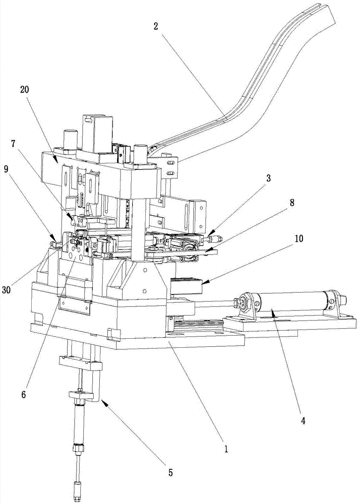
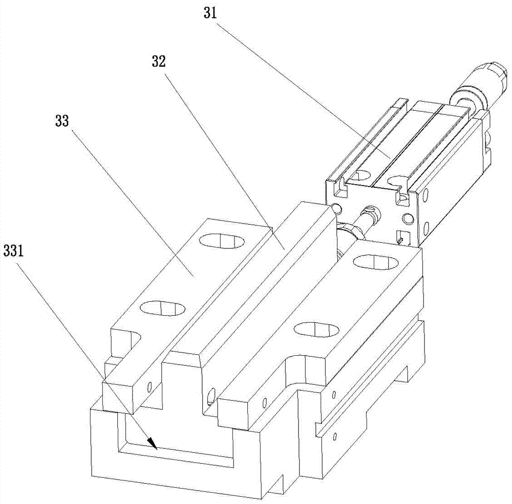
[0043] Such as Figure 1 to Figure 8As shown, a riveting terminal machine provided by the present invention includes a frame 1, a terminal material channel 2 installed on the frame 1, a moving seat 3 slidingly connected to the frame 1, and a mobile seat installed on the moving seat 3. The threading device, the material receiving drive mechanism 5 for driving the mobile seat 3 to receive materials, and the riveting drive mechanism 6 installed on the frame 1, the threading device includes a fire and zero thread threading seat 41, which is opposite to the fire and zero thread threading seat. The live wire threading block 42 and the zero wire threading block 43 provided at 41, the fire and zero ...


PUM


Abstract

The invention relates to the technical field of terminal machining device, in particular to a riveting terminal machine. The riveting terminal machine comprises a rack, a terminal material channel, a moving seat, a threading device, a material catching driving mechanism and a riveting driving mechanism. The threading device comprises a live-null line threading seat, a live line threading block, a null line threading block, a live-null line driving mechanism, a material pushing mechanism, a first ground line threading block, a second ground line threading block, a first ground wire threading driving mechanism and a second ground wire threading driving mechanism. During threading, the material pushing mechanism is used for attaching a terminal to the live-null line threading seat. Live line threading holes and null line threading hones are arranged in the live line threading block, the null line threading block and the live-null line threading seat. Ground line threading holes are arranged in the first ground wire threading block and the second ground wire threading block. According to the invention, material catching of the terminal, threading of three core lines and riveting of the terminal to the three core lines are automatically achieved; production efficiency is improved; labor intensity and production cost are reduced; riveting precision of the terminal to the three core lines is high; and production quality is improved.

Description

technical field [0001] The invention relates to the technical field of terminal processing equipment, in particular to a riveting terminal machine. Background technique [0002] During the production process of existing terminals and three round core wires, it is necessary to manually assemble the terminals and three round core wires, and then manually place the live wire and terminal, neutral wire and terminal, and ground wire and terminal in the riveting Press equipment for riveting. The existing terminal processing method requires a lot of manual processing, which has low production efficiency, high production cost and poor product quality. Contents of the invention [0003] The technical problem to be solved by the present invention is to provide an automatic crimping terminal machine. [0004] In order to solve the above technical problems, the present invention adopts the following technical solutions: [0005] A riveting terminal machine, which includes a frame, ...

Claims


Application Information

Patent Timeline
IPC IPC(8): H01R43/055
CPCH01R43/055Y02E60/10
Inventor 余爱身
Owner 东莞市和众智能设备有限公司
Learn More