Electric power switch cabinet

A power switch and switch room technology, applied in the field of switch cabinets, can solve the problems of cabinet short circuit, staff injury, cabinet damp, etc., and achieve the effects of prolonging service life, ensuring personal safety, and good heat dissipation

Pending Publication Date: 2017-07-28
CHINA SCI TIANGONG ELECTRICAL HLDG
View PDF0 Cites 3 Cited by
  • Summary
  • Abstract
  • Description
  • Claims
  • Application Information

AI Technical Summary

Problems solved by technology

[0002] With the continuous development of society and the continuous development of the electric power industry, all kinds of electric power related equipment are constantly being improved. Take a kind of electric switch cabinet as an example. When using traditional devices of this type, the cabinet body is mostly placed directly on the On the ground, after a long time of use, the cabinet will be damp, which will easily cause a short circuit inside the cabinet and damage the device, which is not conducive to the use of the device. At the same time, the traditional device of this type does not have a vacuum cleaner. After long-term use, the cabinet will deposit A certain amount of dust will affect the use of the device. At the same time, after the device is used for a long time, a large amount of heat is easy to accumulate inside the cabinet, which affects the use of the device. At the same time, traditional devices of this type often steal electricity and cause great losses. , it is not convenient to use the device, and at the same time, the traditional device of this type will have a long-term leakage phenomenon, which is easy to cause injury to the staff after the leakage

Method used


Image

  • Electric power switch cabinet
  • Electric power switch cabinet

Examples


Embodiment Construction

[0013] The following will clearly and completely describe the technical solutions in the embodiments of the present invention with reference to the accompanying drawings in the embodiments of the present invention. Obviously, the described embodiments are only some, not all, embodiments of the present invention. Based on the embodiments of the present invention, all other embodiments obtained by persons of ordinary skill in the art without making creative efforts belong to the protection scope of the present invention.

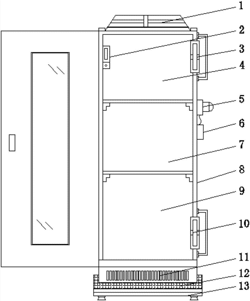
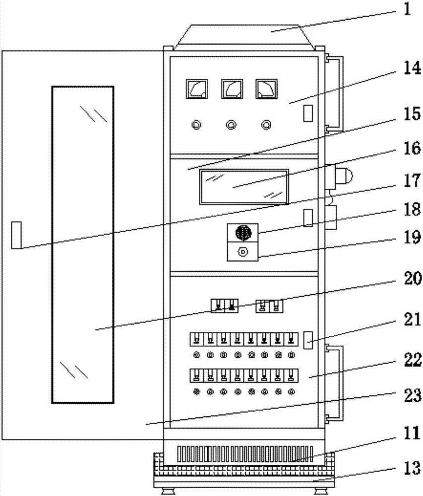
[0014] see Figure 1-2 , an embodiment provided by the present invention: a power switchgear, including a clamping cabinet body 8, a base 13 and a cabinet door 23, the top of the base 13 is provided with a moisture-proof cushion 12, and the top of the moisture-proof cushion 12 is fixed with a cabinet Body 8, a cabinet door 23 is hinged on one side of the cabinet body 8, and a first handle 17 is installed on the cabinet door 23, and the surfaces of the first ha...


PUM


Abstract

The invention discloses an electric power switch cabinet. The switch cabinet comprises a clamp cabinet body, a base and a cabinet door. A moisture-proof cushion layer is arranged on the top end of the base. The cabinet body is fixed on the top end of the moisture-proof cushion layer. The cabinet door is hinged to one side of the cabinet door. A first handle is installed on the cabinet door. A dust collector is installed on the top end of the cabinet door. A third switch chamber is installed on the bottom end in the cabinet body. A third door body is installed on one side, near the cabinet door, of the third switch chamber. A buzzer alarm is installed on the cabinet body between a first draught fan and a second draught fan. A current detector is installed on the cabinet door under the buzzer alarm. The output end of the current detector is electrically connected with the input end of the buzzer alarm through a wire. According to the invention, by installing the base, arranging the moisture-proof layer on the bottom end of the base, and arranging the cabinet body on the base, a phenomenon that the cabinet door suffers from moisture after being used for a long time is avoided; a short-circuit phenomenon does not occur; and service lifetime of the device is prolonged.

Description

technical field [0001] The invention relates to the technical field of switch cabinets, in particular to a power switch cabinet. Background technique [0002] With the continuous development of society and the continuous development of the electric power industry, all kinds of electric power related equipment are constantly being improved. Take a kind of electric switch cabinet as an example. When using traditional devices of this type, the cabinet body is mostly placed directly on the On the ground, after a long time of use, the cabinet will be damp, which will easily cause a short circuit inside the cabinet and damage the device, which is not conducive to the use of the device. At the same time, the traditional device of this type does not have a vacuum cleaner. After long-term use, the cabinet will deposit A certain amount of dust will affect the use of the device. At the same time, after the device is used for a long time, a large amount of heat is easy to accumulate ins...

Claims


Application Information

Patent Timeline
IPC IPC(8): H02B1/30H02B1/28H02B1/56H02B1/32H02B1/38
CPCH02B1/28H02B1/30H02B1/303H02B1/306H02B1/32H02B1/38H02B1/565
Inventor 张云龙阴加花张帆刘雅群马勇张世锦
Owner CHINA SCI TIANGONG ELECTRICAL HLDG
Why Eureka
Try Eureka