A drum automatic cooking machine

An automatic cooking and drum technology, which is applied in the heating device and other directions, can solve the problems of difficult cleaning, too many pots and components, and the inability to cook, and achieve the effect of simple assembly process, avoiding mutual interference, and delicious cooking effect

Active Publication Date: 2021-06-01
JOYOUNG CO LTD
View PDF5 Cites 0 Cited by
  • Summary
  • Abstract
  • Description
  • Claims
  • Application Information

AI Technical Summary

Problems solved by technology

For the structure with a stirrer, since the stirrer is installed in the pot, there are many components in the pot, which are uneven and difficult to clean, and when cooking strips of food, it will cause entanglement, resulting in failure to cook
For air flow stirring, when cooking food, it will cause clogging of food residue or oil, resulting in poor exhaust, and it is not easy to clean after clogging
[0003] In order to solve the above problems, a cooking machine with a drum structure such as CN201520275651.1 has appeared in the field of household appliances to cook food, but this structure only heats the side wall of the pot, and the drive motor in this patent is affected by the magnetic field of the electromagnetic coil ,There are security risks

Method used


Image

  • A drum automatic cooking machine
  • A drum automatic cooking machine
  • A drum automatic cooking machine

Examples


Embodiment approach 1

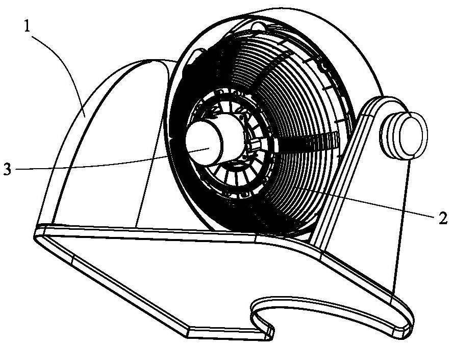
[0033] see figure 1 , figure 2 as well as image 3 As shown, a drum automatic cooking machine according to the present invention includes a body 1 , an electromagnetic coil 2 , a pot (not shown in the figure), and a drive motor 3 for driving the rotation of the pot. The pot is located on the electromagnetic coil 2 .

[0034] The body 1 supports the electromagnetic wire tray 2 and the inner pot, so that the drum automatic cooking machine of the present invention can be tilted when cooking, and can be in a non-cooking state or cooking soup and porridge in a vertical state.

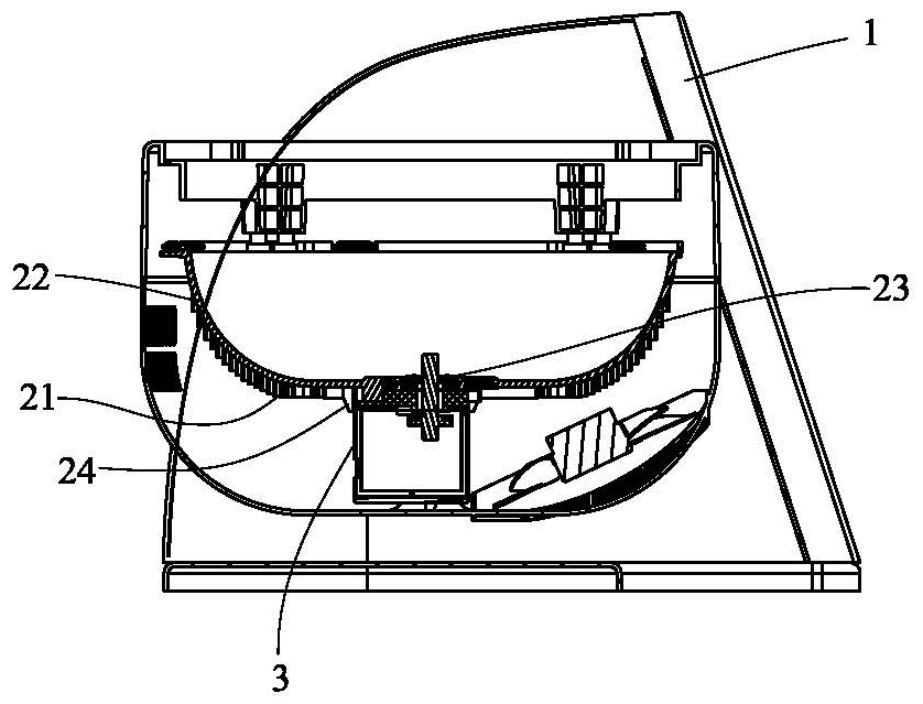
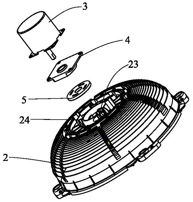
[0035] The electromagnetic coil includes a bottom wall 21 that is a side wall 22 adapted to the shape of the inner pot. The middle part of the bottom wall 21 is provided with a through hole 23 for the output shaft of the drive motor to pass through. The outer periphery of the through hole 23 is provided with a support limiter. Rib 24, the driving motor 3 is fixed within the range limited by the support li...

Embodiment approach 2

[0056] see Figure 4 As shown, the second embodiment of the drum automatic cooking machine of the present invention differs from the first embodiment in that the number of winding layers of the side induction coil 27 is greater than that of the bottom induction coil 26 .

[0057] In this way, it is further ensured that the arc-shaped side wall of the electromagnetic induction coil of the present invention generates more heat than the bottom wall, thereby ensuring the effect of three-dimensional heating.

[0058] Further, the winding layers of the side induction coil 27 are 2-4 layers, and the winding layers of the bottom induction coil 26 are 1-2 layers. Of course, the winding of the side induction coil 27 can also have more local layers, for example, the middle of the side induction coil 27 has more layers than the two sides, or the layers are arranged alternately. In general, it can ensure that the heat of the side induction coil 27 is greater than that of the bottom induct...


PUM


Abstract

The invention relates to a drum automatic cooking machine. The electromagnetic wire tray includes a bottom wall that is adapted to the shape of the inner pot. A through hole is provided in the middle of the bottom wall for the output shaft of the driving motor to pass through. There are support limit ribs, and the drive motor is fixed within the range limited by the support limit ribs. In this way, the driving motor can be fixed more reliably, and the influence of the magnetic field on the motor can be more effectively reduced within the range limited by the supporting ribs, and the assembly process is relatively simple.

Description

technical field [0001] The invention belongs to the field of kitchen appliances, and in particular relates to a drum automatic cooking machine. Background technique [0002] Most of the electric cooking utensils currently on the market include a pot liner and a shell. The pot liner is placed in the shell. During the cooking process, it remains still and relies on the boiling of water to stir the food or absorb water by itself to achieve the cooking effect. In order to pursue a better cooking effect, cooking utensils with stirring devices have appeared, such as cooking machines with stirrers, rice cookers with airflow or stirrers. For the structure in which the stirrer is set, since the stirrer is set in the inner pot, there are many devices in the inner pot, which are uneven and difficult to clean, and when cooking strip-shaped food, it will cause entanglement, resulting in failure to cook. For air flow stirring, when cooking food, it will cause clogging of food residue or ...

Claims


Application Information

Patent Timeline
Patent Type & Authority Patents(China)
IPC IPC(8): A47J36/24
CPCA47J36/24
Inventor 朱泽春刘远
Owner JOYOUNG CO LTD
Why Eureka
Try Eureka