
Textile mechanical dust removal device

A technology of dust removal device and textile machinery, applied in textiles and papermaking, water/sludge/sewage treatment, use of liquid separators, etc. The process is fast and stable, the production cost is reduced, and the effect of collection and cleaning is facilitated.

Inactive Publication Date: 2017-08-01
杨露萍
View PDF4 Cites 8 Cited by
  • Summary
  • Abstract
  • Description
  • Claims
  • Application Information

AI Technical Summary

Problems solved by technology

[0002] With the advancement of science and technology, the quality of human life is gradually improving, and people's requirements for the comfort of the working environment are also getting higher and higher. The lint and dust are produced, causing serious environmental pollution and affecting the human health of the operators. At the same time, these lint and dust will be scattered and accumulated on the machinery, causing failure of the mechanical equipment, and will also be scattered to other production products, resulting in relatively poor production. Poor pollution, affecting the quality of production
[0003] In the existing technology, simply installing fans and other devices in the production environment cannot effectively eradicate impurities, and simple blowing without treatment cannot solve the residual impurities in the air
[0004] In the existing technology, the best way to use a vacuum device to collect impurities is to use a water bath for treatment. The water bath method is simple to install, but the existing devices generally consume too much water, which does not meet the concept of energy saving and emission reduction.

Method used

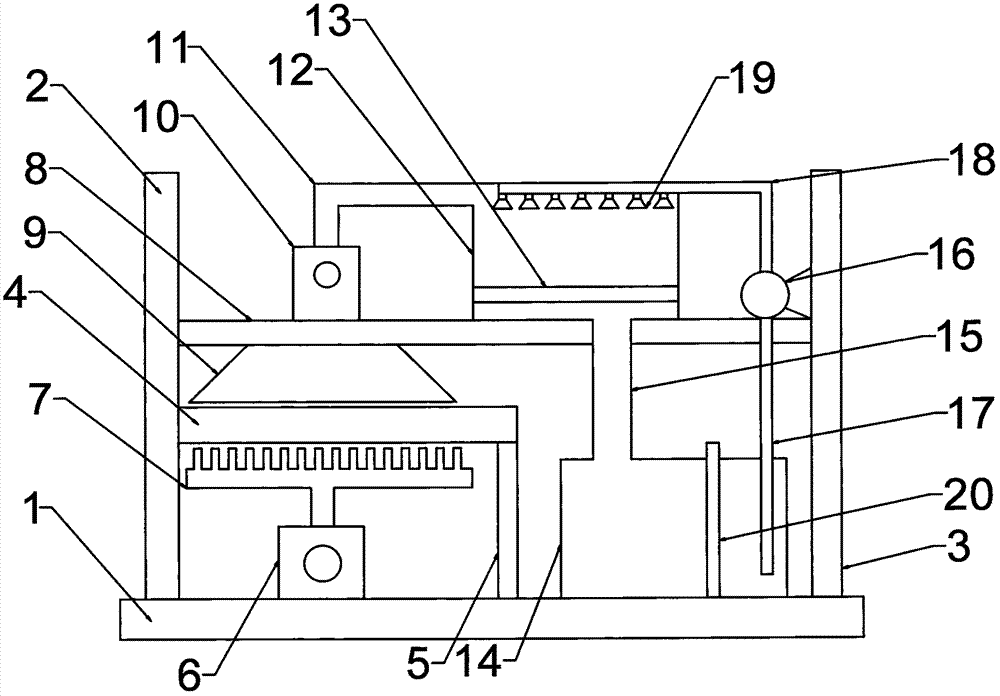
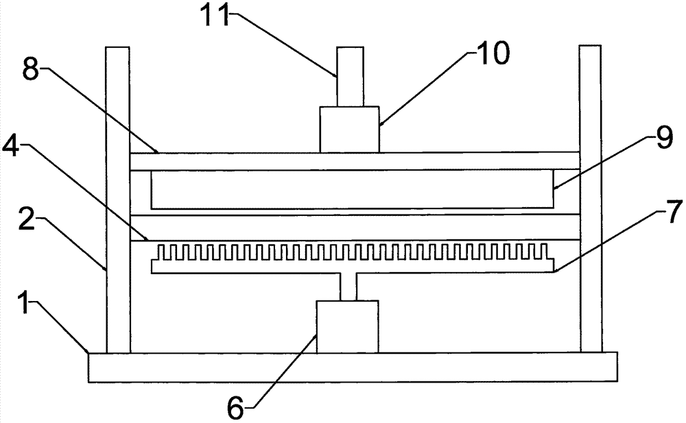
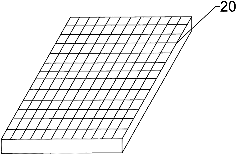

Image

  • Textile mechanical dust removal device
  • Textile mechanical dust removal device
  • Textile mechanical dust removal device

Examples


Embodiment Construction

[0021] The following will clearly and completely describe the technical solutions in the embodiments of the present invention with reference to the accompanying drawings in the embodiments of the present invention. Obviously, the described embodiments are only some, not all, embodiments of the present invention. Based on the embodiments of the present invention, all other embodiments obtained by persons of ordinary skill in the art without making creative efforts belong to the protection scope of the present invention.

[0022] see Figure 1~3 , in an embodiment of the present invention, a textile machinery dust removal device includes a base 1, a left column 2 is provided at the upper left end of the base 1, a right column 3 is provided at the upper right end of the base 1, and a middle part of the left column 2 is provided Weaving workbench 4, the left end of the weaving workbench 4 is connected to the left column 2, the weaving workbench 4 is parallel to the base 1, and the...


PUM


Abstract

The invention discloses a textile mechanical dust removal device which comprises a base, a left upright column, a right upright column, a textile workbench, a horizontal platform and a water pump; a supporting column is arranged at the lower part of the right end of the textile workbench; an air blower is arranged on the left side of the upper part of the base; a blowhole platform is arranged at the upper part of the air blower; an air suction opening is formed in the left side of the lower end of the horizontal platform; an exhaust fan is arranged on the left side of the upper end of the horizontal platform; a ventilation pipe is arranged at the air outlet end of the upper end of the exhaust fan; the right end of the ventilation pipe is provided with a dust accumulation tank in a connecting manner; a filter screen is arranged at the lower part in the dust accumulation tank; a water tank is arranged on the right side of the upper part of the base; and a double-layer filter plate is vertically arranged in the water tank. According to the textile mechanical dust removal device, by matching densely distributed air blowing pipelines with the exhaust fan at the upper end, thread ends, fluffs and dust generated in the textile process can be rapidly and effectively eliminated, and the quality of production can be effectively improved.

Description

technical field [0001] The invention relates to a textile machinery supporting facility, in particular to a textile machinery dust removal device. Background technique [0002] With the advancement of science and technology, the quality of human life is gradually improving, and people's requirements for the comfort of the working environment are also getting higher and higher. The lint and dust are produced, causing serious environmental pollution and affecting the human health of the operators. At the same time, these lint and dust will be scattered and accumulated on the machinery, causing failure of the mechanical equipment, and will also be scattered to other production products, resulting in relatively poor production. Poor pollution affects the quality of production. [0003] In the existing technology, simply installing fans and other devices in the production environment cannot effectively eradicate impurities, and simple blowing without treatment cannot solve the r...

Claims


Application Information

Patent Timeline
IPC IPC(8): B01D47/06C02F1/00D01H11/00C02F103/18
CPCB01D47/06B01D2258/02C02F1/001C02F2103/18D01H11/005
Inventor 杨露萍
Owner 杨露萍
Learn More