Full-automatic steel bar forming device

A fully automatic and reinforced technology, which is applied in construction, building structure, and construction material processing, etc., can solve problems such as labor-intensive, low degree of automation, and increased construction costs, and achieve cost-saving effects

Active Publication Date: 2017-08-01
左红
View PDF8 Cites 5 Cited by
  • Summary
  • Abstract
  • Description
  • Claims
  • Application Information

AI Technical Summary

Problems solved by technology

[0002] With the development of society and the advancement of human civilization, modern buildings emerge in endlessly, and building construction is becoming more and more intelligent. People's requirements for housing construction are also becoming more and more diverse. Residential communities, villages, and small buildings are very suitable for human habitation; but , due to the long construction period of the house, the high cost, especially the high labor cost, therefore, the construction cost has been increased. If we want to reduce the cost and build a good house in a short period of time, we must rely on science and technology, advanced and excellent equipment and management personnel; now all industries in our country All industries are constantly developing and innovating, facing the world and developing economies with good contacts with other countries, and the construction industry is no exception. In order to go global, we used extensive management methods in the past, taking advantage of large numbers of people, low labor costs, and cheap prices to integrate Competing with foreign counterparts, paying more and paying less, it is difficult to occupy

Method used


Image

  • Full-automatic steel bar forming device
  • Full-automatic steel bar forming device
  • Full-automatic steel bar forming device

Examples


Embodiment Construction

[0026] The present invention will be further described below in conjunction with the drawings and specific embodiments:

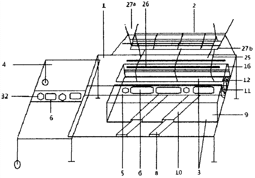
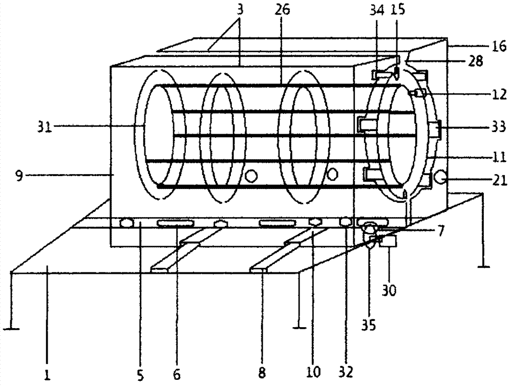
[0027] In specific implementation, such as Figure 1-Figure 5 According to the formula, the full-automatic steel bar tying equipment of the present invention includes a working table 1, a material support 2, and a steel bar tying device 3. One end of the working table is provided with a telescopic table 4, and a groove 5 is longitudinally provided on the working table. There are more than two strip rollers 6, the work surface under the strip rollers 6 is provided with more than two holes 7, and the work surface is transversely provided with two or more slide rails 8. The steel bar binding device 3 is divided into two types: movable and fixed. There are two parts. The bottom of the movable part 9 is provided with a sliding groove 10 opposite to the sliding rail 8. There are two or more arc-shaped rings 11 in the steel bar binding device 3, and two or more mecha...


PUM


Abstract

The invention discloses a full-automatic steel bar forming device. The full-automatic steel bar forming device is characterized in that the full-automatic steel bar forming device comprises a workbench, a material support and a steel bar binding unit. One end of the workbench is provided with a retractable table, the surface of the workbench is provided with a groove and a slide rail, and the groove is internally provided with two or more strip-shaped rollers. The steel bar binding unit is divided into a movable part and a fixed part, a slide groove is formed in the bottom of the movable part and opposite to the slide rail, and the steel bar binding unit is internally provided with two or more arc rings. Two or more mechanical arms are arranged on the periphery of each arc ring, mechanical hands are arranged at the front ends of the mechanical arms, and a notch is formed below each arc ring. Electromechanical welding guns are arranged at the top and bottom of each arc ring of the movable part of the steel bar binding unit, circular strip transformation components are arranged at the notches of the arc rings of the fixed part of the steel bar binding unit, and an inlet is formed below the circular strip transformation components and provided with two rotary gears. The full-automatic steel bar forming device is high in automation degree, can replace manual binding forming with an intelligent machine for steel bar forming, is safe and reliable, saves the time and labor and can effectively increase the labor production rate.

Description

Technical field [0001] The invention belongs to the field of construction, in particular, it relates to a fully automatic steel forming equipment widely used in the construction process. Background technique [0002] With the development of society and the progress of human civilization, modern buildings are emerging in endlessly, and building construction is becoming more and more intelligent. People's requirements for housing construction are becoming more and more diversified. Residential areas, villages, and small buildings are very suitable for human living; but Due to the long construction period and high cost, especially the high labor cost, the construction cost is increased. If you want to reduce the cost and build a house in a short period of time, you must rely on science and technology, advanced equipment and management personnel; Various industries are constantly developing and innovating. Facing the world to have good contacts with other countries to develop the eco...

Claims


Application Information

Patent Timeline
IPC IPC(8): E04G21/12
CPCE04G21/123
Inventor 左红
Owner 左红
Why Eureka
Try Eureka