A differential linear piezoelectric motor and its working method

A piezoelectric motor, working method technology, applied in piezoelectric effect/electrostrictive or magnetostrictive motors, generators/motors, electrical components, etc., can solve problems such as low positioning accuracy, achieve low production cost, The effect of long life and self-locking after power failure

Active Publication Date: 2019-05-21
东台城东科技创业园管理有限公司
View PDF4 Cites 3 Cited by
  • Summary
  • Abstract
  • Description
  • Claims
  • Application Information

AI Technical Summary

Problems solved by technology

[0008] The purpose of the present invention is to address the defects in the prior art and provide a solution to the contradiction between travel and precision in the field of piezoelectric precision actuation, that is, the positioning accuracy of piezoelectric actuators with large travel (mm order) Low (on the order of μm); and piezoelectric actuators with nanometer precision (including on the order of 10nm) usually have a small stroke (on the order of 0.1mm)

Method used


Image

  • A differential linear piezoelectric motor and its working method
  • A differential linear piezoelectric motor and its working method
  • A differential linear piezoelectric motor and its working method

Examples


Embodiment Construction

[0044] Below in conjunction with accompanying drawing, technical scheme of the present invention is described in further detail:

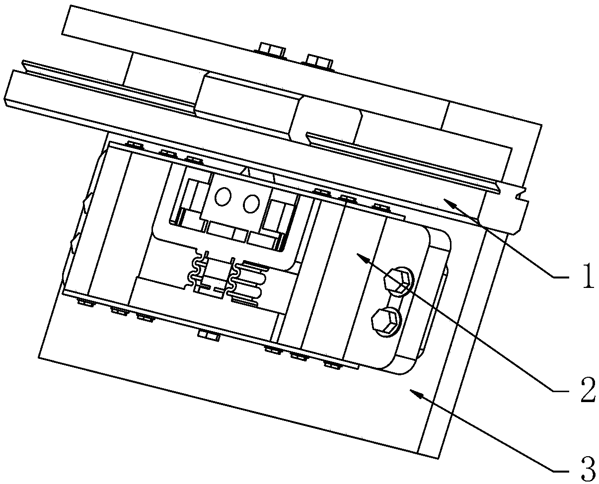
[0045] Such as figure 1 The structure of the differential linear piezoelectric motor shown includes a mover 1, a stator 2 and a base 3; the mover 1 is fixed on the side plate of the base by bolts; the stator 2 is fixed on the bottom plate of the base by bolts; by controlling the stator 2. The front and rear positions of the base can control the initial pressure between the stator 2 and the mover 1.

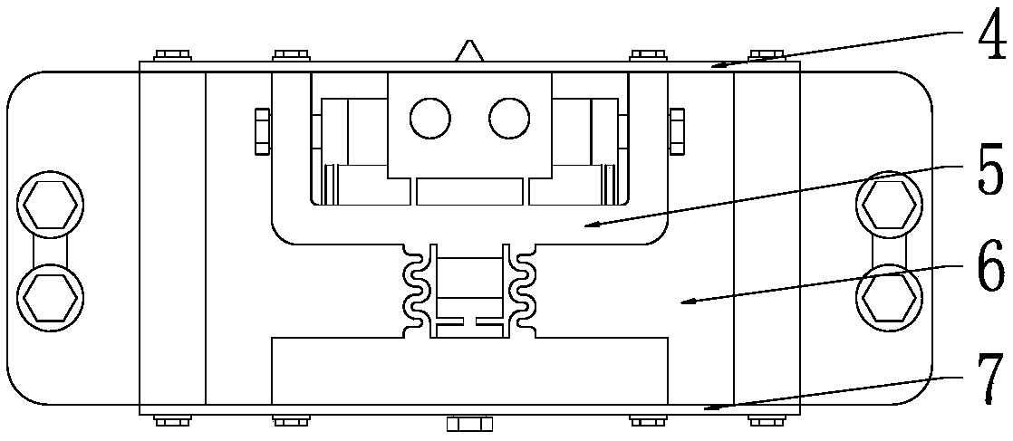
[0046] Such as figure 2 The elastic clamping mechanism shown is two symmetrically arranged pre-compressed leaf springs.

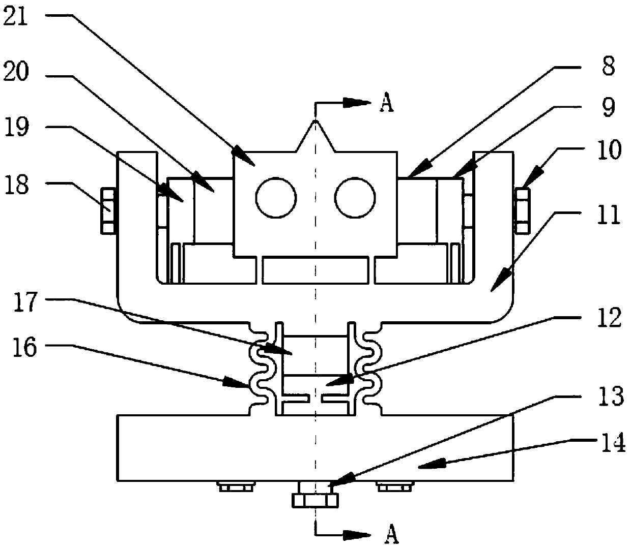
[0047] Such as Image 6 As shown, the preloaded leaf spring includes a ring frame structure, a flexible hinge and a square plate; the short side of the ring frame structure and the square plate are connected by a flexible hinge; the ring frame is provided with threaded holes, which can be fixedly connected with the support 6; th...


PUM


Abstract

The invention discloses a differential linear piezoelectric motor and a working method thereof. A driving foot on a motor stator comprises two groups of symmetric piezoelectric stacking layers parallel with a guide rail, and one group of piezoelectric stacking layers vertical to the guide rail, so as to respectively provide slight vibration in parallel with and vertical to the guide rail direction for the stator driving foot. The differential linear piezoelectric motor has the advantages that by utilizing symmetric periodic signals to excite piezoelectric stacking layer parallel with the guide rail direction, and rectangular wave signals to excite the piezoelectric stacking layer vertical to the guide rail direction, the friction driving characteristic between the motor stator and a rotor has obvious difference between the driving phase and the return phase, so that the movement distance of the motor in the driving phase is greater than the movement distance in the return phase; because the motor has obvious different differential friction characteristic in the frequency range of 0 to 1KHz, when the driving frequency is changed from low frequency to high frequency, the positioning accuracy of the motor is gradually changed from nanometer level to micrometer level, and the macro-micro combined positioning platform with complicated structure may be replaced.

Description

technical field [0001] The invention relates to a differential linear piezoelectric motor, belonging to the technical field of piezoelectric actuators. Background technique [0002] With the development of micro / nano technology, there is an urgent need for submicron and micro / nano precision actuators in the research of many engineering technology fields. However, because the traditional electromagnetic motor needs a deceleration device, it is difficult to break through in the development direction of miniaturization and high power-to-weight ratio. With the development of material science, new functional materials have proposed new solutions for these applications. Among them, the discovery of the inverse piezoelectric effect and the emergence of piezoelectric ceramic (PZT) materials with superior performance have made piezoelectric precision actuators The research has received extensive attention and has shown broad application prospects in the field of precision motion. ...

Claims


Application Information

Patent Timeline
Patent Type & Authority Patents(China)
IPC IPC(8): H02N2/04H02N2/06
CPCH02N2/04H02N2/06
Inventor 陈西府李明卢倩王正刚周海
Owner 东台城东科技创业园管理有限公司
Why Eureka
Try Eureka