Paper currency processing device

A banknote processing device and banknote technology, which are applied in coin receiving devices, thin material handling, stacking receiving devices, etc., can solve problems such as banknote scattering, storage errors, banknote offset, etc., achieve stable handling force, and prevent movement stoppage , the effect of suppressing offset

Active Publication Date: 2017-08-01
NIPPON CONLUX
View PDF6 Cites 0 Cited by
  • Summary
  • Abstract
  • Description
  • Claims
  • Application Information

AI Technical Summary

Problems solved by technology

[0010] However, in the banknote processing device of Patent Document 2, the conveyance guide is provided on the device main body side, so the banknote cannot be taken out from the banknote storage while the stored banknote is held by the conveyance guide and the pressing plate. When collecting banknotes and replenishing change, it is necessary to press the banknotes on the spring-biased pressure plate with your fingers, and if your fingers leave the banknotes by mistake, the banknotes may be scattered due to the force of the spring.
[0011] In addition, since the banknote storage operation is carried out while the banknotes are held by the conveyance belt and the pressing roller provided in the banknote conveyance path, the banknotes may be shifted during the banknote storage, and storage errors may occur.
In order to reliably push the banknotes into the banknote storage even when the banknotes are misaligned during banknote storage, the maximum moving distance of the stack guide needs to have a margin, which hinders the miniaturization of the device.

Method used


Image

  • Paper currency processing device
  • Paper currency processing device
  • Paper currency processing device

Examples


Embodiment Construction

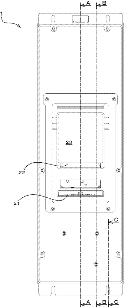
[0040] Below, refer to Figure 1 to Figure 11 The shown figure explains the banknote processing apparatus 1 of an embodiment of this invention. In the following description, first, the structure of the banknote handling device 1 will be described, and then the circulating banknote storage operation and the withdrawal operation in the banknote handling device 1 will be described.

[0041] It should be noted that the banknote processing device 1 has a function of receiving banknotes that can be used for change (hereinafter referred to as circulating banknotes) and large banknotes that are not used for change (hereinafter referred to as non-recycling banknotes), and has a payout cycle Functions of paper money. In addition, in each drawing, the side on which the banknote inlet 21 into which the banknote is inserted is arrange|positioned is defined as the front side.

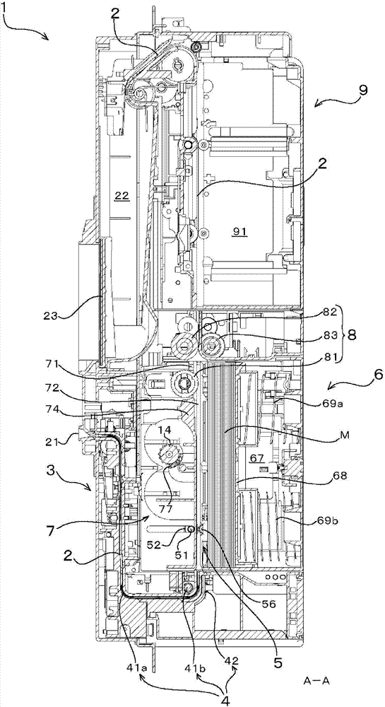
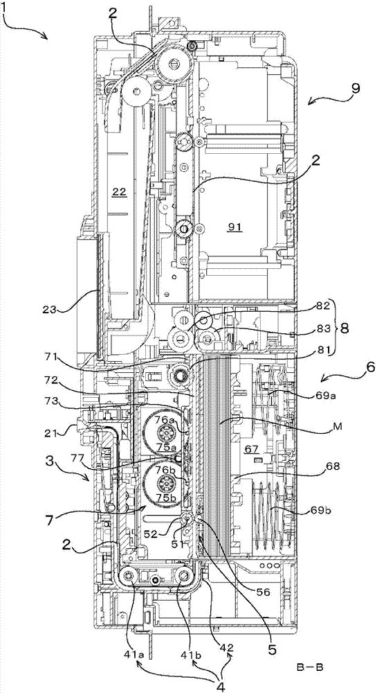
[0042] figure 1 It is a front view of the banknote processing device 1, Figure 2A to Figure 2C Yes figure 1 A-A cross...


PUM


Abstract

Provided is a compact paper currency processing device equipped with a paper currency storage mechanism that stores paper currency in a paper currency storage unit, wherein the paper currency storage unit is removable. This paper currency processing device is equipped with: a stack guide (71) that separates the side edges in the lengthwise direction of paper currency in a paper currency storage compartment (67) and the side edges in the lengthwise direction of paper currency in a paper currency transport passage (2); lift cams (75a), (75b) that reciprocally move the stack guide (71) in a direction substantially perpendicular to the plane surface of the paper currency; a first linking gear (77) for operating these; a transport roller (52) axially supported on the stack guide (71); a second linking gear (53) having the same shaft (51) as the transport roller (52); and a pressing roller (56) axially fixed to the stack guide (71) and arranged opposing the transport roller (52). The pressing roller (56) engages and separates from the transport roller (52) in conjunction with the reciprocal movement of the stack guide (71), and the first and second linking gears (77), (53) respectively transmit driving force from a drive source of the main body via first and second transmission gears (14), (43).

Description

Technical field [0001] The present invention relates to a small banknote processing device equipped with a banknote storage mechanism and mounted on equipment such as automatic vending machines, exchange machines, and unmanned parking lot. In particular, it relates to a banknote storage section that is detachably assembled to the main body of the banknote processing device Technology. Background technique [0002] Generally, a banknote processing device is installed inside the main body of equipment such as automatic vending machines, exchange machines, and unmanned parking lot toll machines that process banknotes. The banknote processing device distinguishes whether the inserted banknotes are genuine or not, and only stores and distinguishes them. Banknotes that are real banknotes. [0003] The banknote processing device is configured to have: a banknote conveying path, which is provided with a banknote conveying mechanism that conveys banknotes inserted from a banknote inlet to ...

Claims


Application Information

Patent Timeline
IPC IPC(8): G07D9/00B65H31/22
CPCB65H31/22G07D9/00B65H2701/1912G07D11/12G07D11/16
Inventor 伊藤幸男大石清
Owner NIPPON CONLUX
Why Eureka
Try Eureka