Compound machine glue tank heat preservation device

A technology of heat preservation device and temperature measurement device, which is applied to devices and coatings that apply liquid to the surface, can solve the problems of easy heat dissipation, preheating, poor heat preservation effect, etc. good effect

Inactive Publication Date: 2017-08-04
JIANGSU HONGHUA SPECIAL EQUIP CO LTD
View PDF7 Cites 3 Cited by
  • Summary
  • Abstract
  • Description
  • Claims
  • Application Information

AI Technical Summary

Problems solved by technology

Existing compound machine glue tanks are generally heated by inlaying electric heating tubes inside, the colloids are not heated uniformly, the electric heating tubes cannot be disassembled, and replacement is inconvenient. Preheating, directly adding lower temperature colloid to the glue tank will easily cause the original high-temperature colloid in the glue tank to cool down rapidly, th

Method used


Image

  • Compound machine glue tank heat preservation device
  • Compound machine glue tank heat preservation device
  • Compound machine glue tank heat preservation device

Examples


Embodiment Construction

[0010] The specific content of the present invention will be described in detail below in conjunction with the accompanying drawings and specific embodiments.

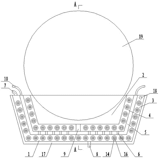
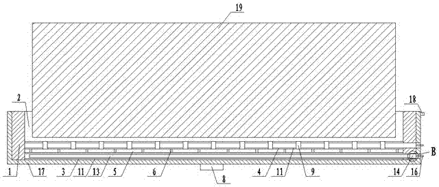
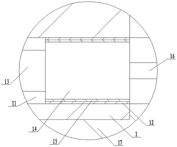
[0011] Such as figure 1 , figure 2 , image 3 As shown, the thermal insulation device of the compound machine glue tank includes: a base 1 and a U-shaped glue tank 2 arranged in the base 1, and an outer U-shaped heat transfer oil chamber 3 and an inner U-shaped heat transfer oil chamber are respectively arranged inside the base 1 Cavity 4, a U-shaped colloid preheating chamber 5 is provided in the base 1 between the U-shaped heat-conducting oil chamber 3 and the inner U-shaped heat-conducting oil chamber 4, and the outer U-shaped heat-conducting oil chamber 3 and the inner U-shaped heat-conducting oil chamber The middle part of the lower end of the oil chamber 4 communicates with each other through a number of heat transfer oil connecting pipes 6 arranged in the U-shaped colloid preheating chamber 5 , and the base 1...


PUM


Abstract

The invention discloses a compound machine glue tank heat preservation device. The device comprises a base and a U-shaped glue tank arranged in the base. The base is internally provided with an outer U-shaped heat conduction oil cavity and an inner U-shaped heat conduction oil cavity. A U-shaped glue preheating cavity is arranged in the base and located between the outer U-shaped heat conduction oil cavity and the inner U-shaped heat conduction oil cavity. The middle of the lower end of the outer U-shaped heat conduction oil cavity and the middle of the lower end of the inner U-shaped heat conduction oil cavity communicate through a plurality of heat conduction oil connecting pipes arranged intelligent the U-shaped glue preheating cavity. A heat conduction oil inlet communicating with the outer U-shaped heat conduction oil cavity is arranged on the base and located on one side of the upper end of the outer U-shaped heat conduction oil cavity. An oil outlet communicating with the outer U-shaped heat conduction oil cavity is arranged on the base and located at the lower end of the outer U-shaped heat conduction oil cavity. The middle of the lower end of the U-shaped glue preheating cavity communicates with the U-shaped glue tank through a plurality of glue connecting pipes arranged in the inner U-shaped heat conduction oil cavity.

Description

technical field [0001] The invention relates to a composite device, in particular to a thermal insulation device for a glue tank of a composite machine. Background technique [0002] Composite machines are used in clothing fabrics, automotive interiors, leather, belts, conveyor belts and other industries. When the composite machine is composited, the materials need to be glued by the rubber roller first, so the glue tank used in conjunction with the rubber roller Glue effect is very important. Existing compound machine glue tanks are generally heated by inlaying electric heating tubes inside, the colloids are not heated uniformly, the electric heating tubes cannot be disassembled, and replacement is inconvenient. Preheating, directly adding lower temperature colloid to the glue tank will easily cause the original high-temperature colloid in the glue tank to cool down rapidly, the overall temperature of the colloid will drop, and the gluing temperature of the gluing roller c...

Claims


Application Information

Patent Timeline
IPC IPC(8): B05C11/11B05C9/14
CPCB05C9/14B05C11/11
Inventor 朱加前
Owner JIANGSU HONGHUA SPECIAL EQUIP CO LTD
Why Eureka
Try Eureka