
Eureka
For R&D, Eureka makes reading and utilizing patents & technical documents easy.
Eureka AIR
Designed for self-driven R&D workflows. Generate viable solutions, solve complex R&D challenges, empower your innovation with AI.

Eureka Materials
Designed for material experts only. Revolutionize your material R&D, from search, analyze, to developing new materials.

TechResearch
Generate reliable direction feasibility study reports for your R&D in just a few steps.

TechSeek
Discover and master advanced knowledge NOW. Basics, ideas, possibilities, all at once.

TechMind
As an expert in R&D Theories, TechMind can generates customized viable solutions instantly.

TechRisk
Analyze your overall solution with one click, know your potential R&D risks in advance.

TechMonitor
Get weekly tech updates, stay abreast of the latest tech innovations and key insights.
Part forging mould convenient to take off
A technology that facilitates taking and forging parts. It is used in manufacturing tools, forging/pressing/hammer devices, forging/pressing/hammering machines, etc. It can solve problems such as difficulty in taking die, simplify the process, improve the forging effect, and avoid potential safety hazards. Effect
- Summary
- Abstract
- Description
- Claims
- Application Information
AI Technical Summary
Problems solved by technology
Method used
Image

Examples
Embodiment 1
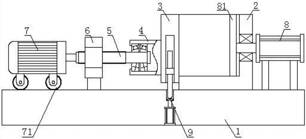
[0025] Such as figure 1 As shown, the present invention includes a base 1, a mold main body 2 is installed on the base 1, a sealing plate 3 is arranged on one side of the mold main body 2, a connecting pipe 4 is fixed on the sealing plate 3, and the connecting pipe 4 is connected with a wire through a bevel gear set. The bar 5 and the leading screw 5 are threadedly connected with a nut 6, and the nut 6 is fixed on the base 1.
[0026] The present invention seals one side of the mold main body 2 through the sealing plate 3. When the mold needs to be taken, by turning the lead screw 5, the lead screw 5 drives the connecting pipe 4 to move, and the connecting pipe 4 drives the sealing plate 3 to move, so that the sealing plate 3 and The mold main body 2 is separated to realize mold opening. The connecting pipe 4 is connected with the leading screw 5 through a bevel gear set, so that the connecting pipe 4 only moves with the leading screw 5 and does not rotate with the leading sc...
Embodiment 2
[0028] On the basis of Embodiment 1, a rotating motor 7 is arranged above the base 1, and a roller 71 is installed on the rotating motor 7. The roller 71 is located above the base 1, and the output shaft of the rotating motor 7 and the lead screw 5 are far away from the sealing plate 3. Fixed connection at one end.
[0029] Lead screw 5 is driven to rotate by rotating motor 7, has realized automatic operation. When the rotating motor 7 rotates, the output shaft of the rotating motor 7 drives the lead screw 5 to rotate in the nut 6, so that the lead screw 5 moves relative to the nut 6, and the lead screw 5 moves to drive the connecting pipe 4 and the sealing plate 3 to move, realizing automatic opening mold.
Embodiment 3
[0031] On the basis of Embodiment 1 or Embodiment 2, a demoulding cylinder 8 is fixed on the base 1, and the demoulding cylinder 8 is located on the side of the mold body 1 away from the sealing plate 3, and the piston rod of the demoulding cylinder 8 and the mold body 2. Connected by a bearing, the piston rod of the demoulding cylinder 8 stretches into the end of the mold body 2 and is fixed with a push plate 81.
[0032] After the sealing plate 3 opens the mold main body 2, the demoulding cylinder 88 is started, and the demoulding cylinder pushes the push plate 81, and the push plate 81 pushes out the forging from the opening position of the mold main body 2. This method of taking molds is easy to operate, and can quickly realize the demoulding of forgings.
PUM
 Abstract
Description
Claims
Application Information
 - R&D Engineer
- R&D Manager
- IP Professional
- Industry Leading Data Capabilities
- Powerful AI technology
- Patent DNA Extraction
Browse by: Latest US Patents, China's latest patents, Technical Efficacy Thesaurus, Application Domain, Technology Topic, Popular Technical Reports.
© 2024 PatSnap. All rights reserved.Legal|Privacy policy|Modern Slavery Act Transparency Statement|Sitemap|About US| Contact US: help@patsnap.com