Al technical title is built by PatSnap Al team. It summarizes the technical point description of the patent document.
An electro-permanent magnetic chuck, integrated technology, applied in the direction of clamping, supporting, positioning device, etc., can solve the problems of easy water entry of magnetic disk, no automatic induction detection, small magnetic attraction and so on
Active Publication Date: 2017-08-04
东莞市耐斯机械制造有限公司
View PDF7 Cites 3 Cited by
Summary
Abstract
Description
Claims
Application Information
AI Technical Summary
This helps you quickly interpret patents by identifying the three key elements:
Problems solved by technology
Method used
Benefits of technology
Problems solved by technology
[0002] At present, most of the disk surface structures on the market are equipped with grooves to install the excitation coil, reversible magnet, permanent magnet and excitation core. When the excitation coil, reversible magnet, permanent magnet and excitation core are installed After the completion, the staff pours sealant into the groove. Since the groove is filled with sealant, when the disk is heated up, the sealing effect between the sealant and the disk is poor, causing the disk to easily enter water and easily cause excitation inside the disk. The coil leaks electricity, which affects the service life of the disk, and the existing disk does not have the function of automatic induction detection, resulting in poor positioning accuracy, poor magnetic effect, weak magnetic attraction, and small magnetic attraction. The magnetic attraction force of the disk is generally only 10KG-15KG
Method used
Image
Click on the blue label to locate the original text in one second.
Reading with bidirectional positioning of images and text.
Examples
Embodiment Construction
[0018] In order to facilitate the understanding of the present invention, the present invention will be described more fully below with reference to the associated drawings. Preferred embodiments of the invention are shown in the accompanying drawings. However, the present invention can be embodied in many different forms and is not limited to the embodiments described herein. On the contrary, the purpose of providing these embodiments is to make the disclosure of the present invention more thorough and comprehensive.
[0019] Unless otherwise defined, all technical and scientific terms used herein have the same meaning as commonly understood by one of ordinary skill in the technical field of the invention. The terminology used herein in the description of the present invention is only for the purpose of describing specific embodiments, and is not intended to limit the present invention.
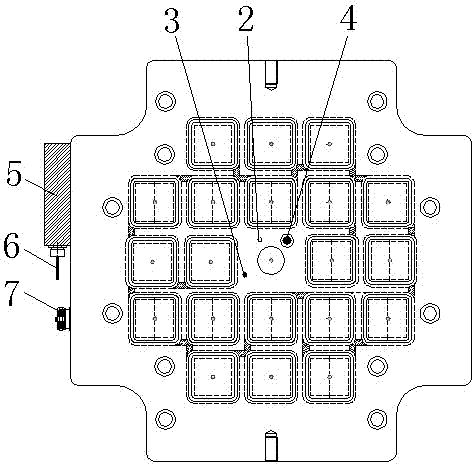
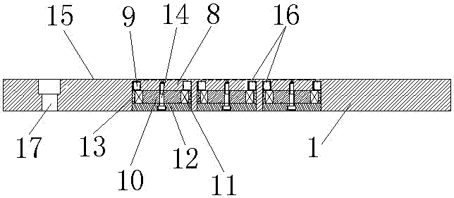
[0020] In this example, refer to Figure 1 to Figure 5 As shown, the integrally forme...
PUM
Abstract
The invention discloses an integrally formed electromagneto chuck which is applied to injection molding machine quick-change mold systems, grinding machines, CNC machining and other machining. The integrally formed electromagneto chuck comprises a magnetic chuck body, a temperature sensor, a magnetic flux sensor, a proximity sensor, a sensor integrated base, sensor connecting lines, a magnetic chuck power input socket, a mounting groove, a field core, permanent-magnet steel, reversible magnet steel, a magnet exciting coil, a magnetic conductive block and the like. The magnetic face of the magnetic chuck body is integrally formed, the leakproofness is good, water is prevented from entering the magnetic chuck body, the electric leakage phenomenon of the magnet exciting coil in the magnetic chuck body is prevented, compared with common electromagneto disks, the strength of the magnetic face is greatly increased, the service life of the magnetic chuck body is prolonged, various working states of the magnetic chuck body are sensed by arranging the multiple sensors, molds can be rapidly clamped and rapidly discharged through the electromagneto chuck, the magnetic conductive efficiency is high, magnet is high, and magnetic attractive force is high and reaches 15-19 kilograms per square centimeter.
Description
technical field [0001] The invention relates to an integrally formed electric permanent magnetic chuck. Background technique [0002] At present, most of the disk surface structures on the market are equipped with grooves to install the excitation coil, reversible magnet, permanent magnet and excitation core. When the excitation coil, reversible magnet, permanent magnet and excitation core are installed After the completion, the staff pours sealant into the groove. Since the groove is filled with sealant, when the disk is heated up, the sealing effect between the sealant and the disk is poor, causing the disk to easily enter water and easily cause excitation inside the disk. The coil leaks electricity, which affects the service life of the disk, and the existing disk does not have the function of automatic induction detection, resulting in poor positioning accuracy, poor magnetic effect, weak magnetic attraction, and small magnetic attraction. The magnetic force of the magn...
Claims
Application Information
Patent Timeline
Application Date:The date an application was filed.
Publication Date:The date a patent or application was officially published.
First Publication Date:The earliest publication date of a patent with the same application number.
Issue Date:Publication date of the patent grant document.
PCT Entry Date:The Entry date of PCT National Phase.
Estimated Expiry Date:The statutory expiry date of a patent right according to the Patent Law, and it is the longest term of protection that the patent right can achieve without the termination of the patent right due to other reasons(Term extension factor has been taken into account ).
Invalid Date:Actual expiry date is based on effective date or publication date of legal transaction data of invalid patent.