
A jig for assembling server boards

A server board and jig technology, which is applied in the field of jigs for assembling server boards, can solve problems such as stress damage to components on the motherboard, uneven stress on the heat sink glue nails, and inability to assemble vertically. Weight, high work efficiency, and the effect of avoiding uneven force

Active Publication Date: 2019-05-14
ZHENGZHOU YUNHAI INFORMATION TECH CO LTD
View PDF5 Cites 0 Cited by
  • Summary
  • Abstract
  • Description
  • Claims
  • Application Information

AI Technical Summary

Problems solved by technology

[0005] The technical task of the present invention is to provide a jig for assembling server boards to solve problems caused by suspension of the main board in the assembly of existing server boards, damage to components on the main board and uneven force on the rubber nails on the heat sink. The problem of not being able to assemble vertically

Method used


Image

  • A jig for assembling server boards
  • A jig for assembling server boards
  • A jig for assembling server boards

Examples


Embodiment 1

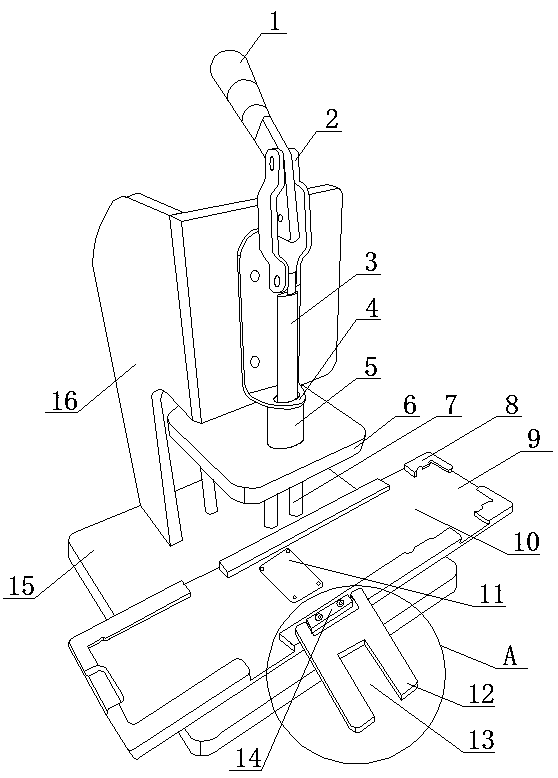
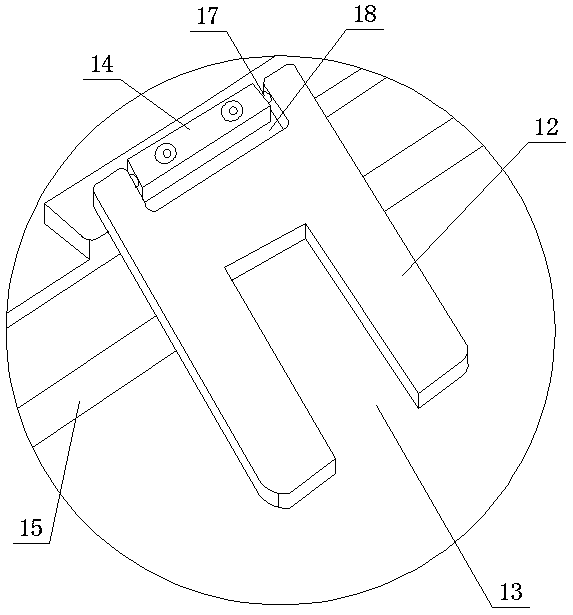
[0036] as attached figure 1 And attached figure 2 As shown, a fixture for assembling server boards of the present invention includes a pressing mechanism, a carrier and a buckle. The pressing mechanism includes a base 15, a bracket 16, a lifting plate 6 and a lifting mechanism. The bracket 16 is vertically fixed on the On the top surface of the base 15, the elevating mechanism is fixed on the top of the base 15 by a support 16, and the elevating plate 6 is fixed on the elevating mechanism, and the elevating mechanism can drive the elevating plate 6 to move up and down above the base 15; Tool plate 8 and carrier sheet 11, the top surface of carrier plate 8 is provided with the main board groove 10 that can accommodate mainboard, and the carrier sheet 11 that is used to place cooling fin is arranged in mainboard groove 10; Buckle includes limit plate 12 One of the side portions of the limiting plate 12 is the connecting side portion of the limiting plate 12, and the connecting...

Embodiment 2

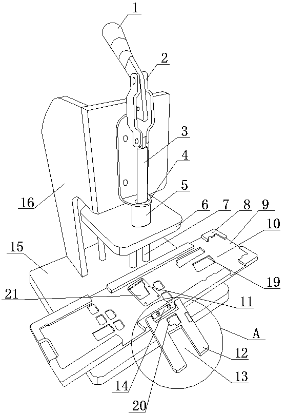
[0052] as attached image 3 And attached Figure 4 As shown, this embodiment is a further improvement on the basis of Embodiment 1. The difference between this embodiment and Embodiment 1 is that a plurality of avoidance grooves I19 are provided on the top surface of the groove 10 of the main board, and the above-mentioned avoidance grooves I19 Respectively correspond to the components on the back of the motherboard to be assembled one by one, so that when the motherboard is placed in the groove 10 of the motherboard, the components on the back of the motherboard are located in the corresponding avoidance groove I19, thereby protecting the back of the motherboard and The safety of components and parts on the main board; the top surface of the carrier sheet 11 is provided with a plurality of avoidance grooves III21, and a plurality of avoidance grooves II20 are provided on the side of the limit plate 12 that can face the carrier sheet 11. The above-mentioned avoidance grooves ...

Embodiment 3

[0055] as attached Figure 5 And attached Figure 6 As shown, this embodiment is a further improvement on the basis of Embodiment 2. The difference between this embodiment and Embodiment 2 is: the carrier plate 8 is provided with a plurality of strip-shaped through holes 22 that run through its top surface and bottom surface. The strip-shaped through holes 22 are distributed in the groove of the main board. The arrangement of the strip-shaped through holes 22 is convenient for reducing the weight of the carrier board 8 .


PUM


Abstract

The invention discloses a jig for assembling a server board, and belongs to the field of server board production jigs. The jig for assembling the server board aims to solve the technical problems that in the existing server board assembling process, a main board gets damaged because of being hung in the air, components and parts on the main board get damaged because of being stressed, and plastic nails on a cooling fin is stressed unevenly and cannot be vertically assembled. The structure of the jig for assembling the server board comprises a pressing mechanism, a carrier and a fastener; the pressing mechanism comprises a base table, a support, a lifting board and a lifting mechanism; the lifting mechanism can drive the lifting board to move up and down above the base table; the carrier comprises a carrier board and a bearing sheet; a main board groove capable of containing the main board is formed in the top surface of the carrier board; the bearing sheet used for placing the cooling fin is arranged in the main board groove; the fastener comprises a limiting board; the connecting side part of the limiting board is rotatably arranged on the end part, close to the bearing sheet, of the carrier board; and a limiting groove penetrating through the bottom surface and the top surface of the limiting board is formed in the limiting side part of the limiting board. The jig for assembling the server board has the advantages that rapid and high-quality assembly of the server board can be realized.

Description

technical field [0001] The invention relates to the field of jigs for server board production, in particular to a jig for assembling server boards. Background technique [0002] Server boards have high requirements on stability and reliability, and any possible component damage will become a hidden danger leading to quality accidents. During the assembly process of server boards, misoperations during the assembly of large metal parts such as heat sinks may touch peripheral components and cause damage to them, causing them to malfunction or die prematurely. The mass production of factories needs to improve production efficiency on the premise of ensuring product quality, and the timeliness optimization of each station is also the goal pursued by every process engineer. [0003] In the traditional method, when assembling the heat sink, the board is placed on the workbench, and the glue nails on the heat sink are pressed by hand or other jigs to complete the assembly. The pro...

Claims


Application Information

Patent Timeline
Patent Type & Authority Patents(China)
IPC IPC(8): B25B27/02
CPCB25B27/02
Inventor 王海滨
Owner ZHENGZHOU YUNHAI INFORMATION TECH CO LTD
Learn More