High-stability hot pressure injection forming system

A high-stability, hot-pressure injection technology, used in ceramic molding machines, auxiliary molding equipment, die-casting molds, etc., can solve the problems of low yield of core hollow blade products, achieve significant improvement effects, and reduce slurry splashing , the effect of improving stability

Pending Publication Date: 2017-08-04
HUAZHONG UNIV OF SCI & TECH
View PDF9 Cites 0 Cited by
  • Summary
  • Abstract
  • Description
  • Claims
  • Application Information

AI Technical Summary

Problems solved by technology

[0005] Aiming at the above defects or improvement needs of the prior art, the present invention provides a highly stable hot pressure injection system, which overcomes the problems caused by equipment factors by setting a heating medium liquid level monitoring device, a solid mold ring and a temperature sensor. The problem of unstable manufacturing process parameters and low yield of corresponding hollow blade products improves the heating efficiency and the stability of process parameters-product performance, reduces the cumbersome steps of disassembling the casing and heating device, and is especially suitable for hollow blades of gas turbines such as aero engines. Mass production of blade cores

Method used


Image

  • High-stability hot pressure injection forming system

Examples


Embodiment 1

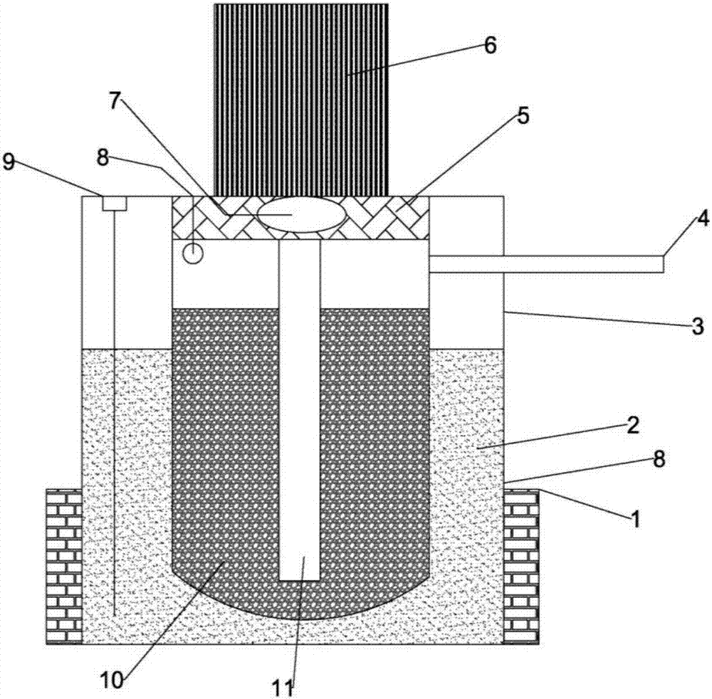
[0032] Open the heating medium liquid level monitoring device 9, and judge the corresponding heating medium addition amount according to the position of the liquid level displayed on the scale. Turn on the power, start the constant temperature heater 1, adjust the power to a certain temperature, heat the heating medium 2 through the heating tank 3, and monitor the temperature in the storage tank / pulp storage tank in real time according to the temperature sensor 8, and wait to be heated to a suitable temperature , start the air circuit device, compressed air at a certain pressure enters the stock tank / slurry tank through the air circuit system 4, and under the action of pressure, the slurry 10 enters the mold 6 from the slurry delivery pipe 11 through the solid mold ring 7, and passes through After a period of grouting and pressurization, close the air circuit device, deflate and take out the mold, condense, and complete an injection molding cycle after demoulding. The hot pres...

Embodiment 2

[0034] Turn on the power, judge and add an appropriate amount of heating medium according to the position of the liquid level displayed on the digital display panel, start the constant temperature heater 1, adjust the power to a certain temperature, heat the heating medium 2 through the heating tank 3, and use the temperature sensor 8 to real-time Monitor the temperature in the storage tank / pulp tank, and when it is heated to a suitable temperature, start the air circuit device, and the compressed air at a certain pressure enters the storage tank / pulp tank through the air system 4, under the action of pressure, the slurry 10 enters the mold 6 from the slurry delivery pipe 11 through the solid mold ring 7. After a period of grouting and maintaining pressure, close the air circuit device, deflate and take out the mold, condense, and complete an injection molding cycle after demoulding.


PUM


Abstract

The invention belongs to the field of ceramic material forming and particularly relates to a high-stability hot pressure injection forming system. The high-stability hot pressure injection forming system comprises a constant temperature heater, a heating trough, a mold, slurry and the like. The heating trough is of an interlayer structure. A slurry containing trough is arranged in the heating trough, and the slurry is contained in the slurry containing trough. A heating medium is injected into an interlayer of the heating trough. The constant temperature heater is attached to the periphery of the heating trough. A heating medium liquid level monitoring device is further arranged on one side of the heating trough. The slurry containing trough is sealed through a material storage cover located at the top of the heating trough. The mold is tightly arranged on the upper surface of the material storage cover. One end of a slurry conveying pipe penetrates through the material storage cover to communicate with the mold, and the other end of the slurry conveying pipe extends into the inner bottom end of the heating trough. A through hole lead-in gas path system is further arranged at the upper end of the heating trough. Through the high-stability hot pressure injection forming system, the heating medium liquid level can be monitored at any time, a proper amount of the heating medium is injected as required, and the heating efficiency and process parameter-product performance stability are improved.

Description

technical field [0001] The invention belongs to the field of ceramic material molding, and more specifically relates to a high-stability hot-press injection molding system, which can monitor the liquid level of the heating medium at any time and pour in an appropriate amount of heating medium as needed to improve heating efficiency and process parameters-products Stable performance. Background technique [0002] The basic purpose of the hot pressure injection system is to inject the waxy slurry with a certain solid content into the cavity of the mold under pressure to form a blank with a specific shape after condensation. It is widely used in the batch manufacturing process of hollow blade cores of aeroengine gas turbines. Especially when the inner hole of the turbine hollow blade is complex and fine and the edge is as thin as 0.3mm, the ceramic core for investment casting with good surface quality, high dimensional accuracy and complex shape can be obtained in batches by u...

Claims


Application Information

Patent Timeline
Patent Type & Authority Applications(China)
IPC IPC(8): B28B1/26B28B17/00
CPCB28B1/262B28B17/0081
Inventor 史玉升胡永刚吴甲民魏青松刘洁
Owner HUAZHONG UNIV OF SCI & TECH
Why Eureka
Try Eureka