Slip sheet of vane type compressor and vane type compressor

A compressor and rotary vane technology, applied in the field of compressors, can solve the problem of large bias force of the sliding vane, and achieve the effects of improving the service life, preventing excessive friction loss, and reducing frictional power consumption.

Active Publication Date: 2017-08-04
ZHUHAI GREE REFRIGERATION TECH CENT OF ENERGY SAVING & ENVIRONMENTAL PROTECTION
View PDF5 Cites 7 Cited by
  • Summary
  • Abstract
  • Description
  • Claims
  • Application Information

AI Technical Summary

Problems solved by technology

[0004] Therefore, the technical problem to be solved by the present invention is to overcome the defect that the sliding vanes in the prior art suffer from a relatively large bias force, thereby providing a sliding vane and a rotary vane compressor. compressor

Method used


Image

  • Slip sheet of vane type compressor and vane type compressor
  • Slip sheet of vane type compressor and vane type compressor
  • Slip sheet of vane type compressor and vane type compressor

Examples


Embodiment 1

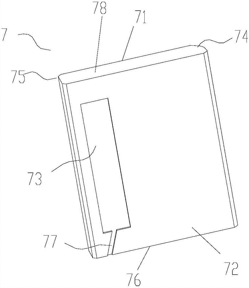
[0042] Such as figure 1 As shown, the present invention provides a sliding vane 7 of a rotary vane compressor, which includes: a first side 71 and a second side 72, wherein the first side 71 and the second side 72 are arranged opposite to each other, and at the A side oil groove 73 capable of accommodating high-pressure oil is provided on the second side 72, and the side oil groove 73 is opened from the second side 72 in a direction toward the first side 71, and does not pass through the first side. 71.

[0043]On the second side of the oppositely arranged first and second sides of the sliding plate, a side oil groove is opened toward the first side but does not pass through the first side, and the side oil groove contains high-pressure oil, which can pass through the The side oil tank is filled with high-pressure oil, so that the pressure vertical to the slide can be formed on the second side of the slide to balance or reduce the bias force generated by the front end of the ...

Embodiment 2

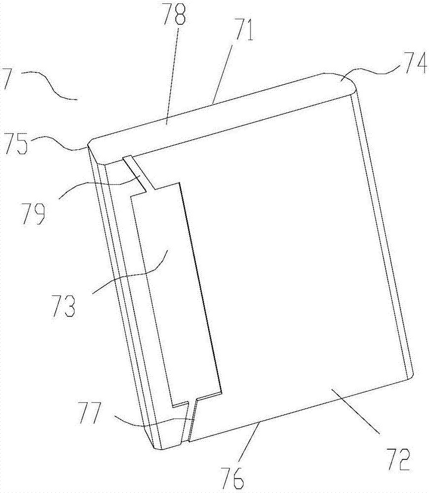
[0048] Such as figure 2 As shown, this embodiment is a further improvement made on the basis of Embodiment 1, which belongs to the means added on the basis of the technical solution of Embodiment 1. Preferably, an end is also provided on the second side 72 The second oil groove channel 79 communicates with the side oil groove 73 and extends to the upper end surface 78 at the other end. By setting up a second oil groove channel connected to the side oil groove on the upper end surface of the slide plate, oil can be supplied to the side oil groove through the second oil groove channel, and combined with the first oil groove, oil can be supplied to the side oil groove through two oil grooves at the same time. It is also possible to supply oil to the side oil tank separately through the first or second oil tank, which is a preferred way of oil supply, which can realize the supply of high-pressure oil and generate the effect of high-pressure oil pressure, in order to reduce and pr...

Embodiment 3

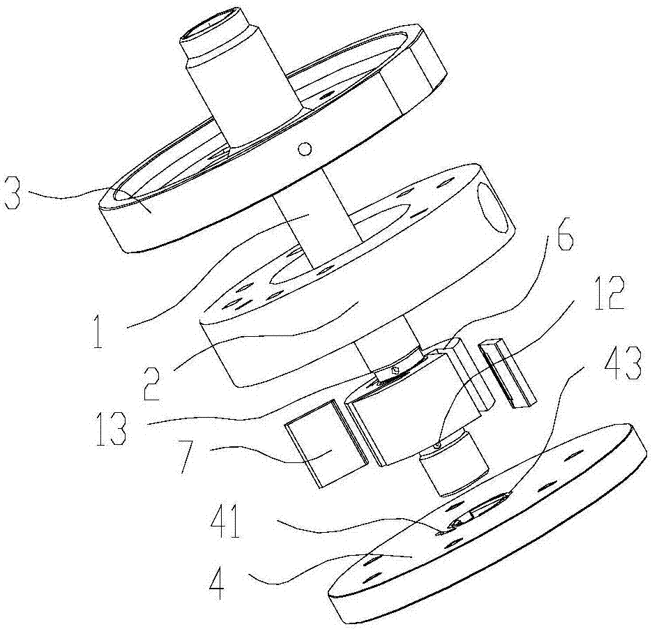
[0050] Such as Figure 3-7 As shown, the present invention also provides a rotary vane compressor, which includes: a main shaft 1; a cylinder 2; an upper flange 3; a lower flange 4; a cylinder cavity 5 formed between the main shaft 1 and the cylinder 2 between; sliding vane slot 6, which is opened on the main shaft 1 (preferably there are more than 3 sliding vane slots);

[0051] It also includes the aforementioned slide piece 7 (one slide piece 7 is correspondingly arranged in each slide piece groove 6), the slide piece is accommodated in each slide piece groove 6, and the first side 71 is located at the The upstream side of the rotation direction of the main shaft 1, the second side surface 72 is located on the downstream side of the rotation direction (such as Figure 8 As shown, the main shaft rotates clockwise, the upstream side of the rotation direction is the left side of the slide plate 7, and the downstream side of the rotation direction is the right side of the slid...


PUM


Abstract

The invention provides a slip sheet of a vane type compressor and the vane type compressor. The slip sheet comprises a first side face (71) and a second side face (72), wherein the first side face (71) and the second side face (72) are arranged back to back; a side face oil groove (73) for accommodating high pressure oil is formed in the second side face (72); and the side face oil groove (73) is formed in the direction towards the first side face (71) from the second side face (72) and does not penetrate through the first side face (71). According to the invention, high pressure oil can be fed in through the side face oil groove, so that pressure perpendicular to the slip sheet is formed on the second side face of the slip sheet to balance or reduce biasing force, moment of force is enabled to reach balance as much as possible, the slip sheet is prevented from abnormal abrasion generated by line contact formed between the slip sheet and a slip sheet notch due to the biasing force, surface contact is formed, the service life of the slip sheet is prolonged to certain degree, and the frictional power consumption at the part is reduced, wherein the biasing force is generated when the front end of the slip sheet is subjected to pressure of a high-pressure cavity and a lower-pressure cavity on two sides.

Description

technical field [0001] The invention belongs to the technical field of compressors, and in particular relates to a sliding vane and a rotary vane compressor of a rotary vane compressor. Background technique [0002] The existing traditional rotary vane compressor usually has more than 3 sliding vanes, because the sliding vanes will be affected by the back pressure of the sliding vanes and the pressure difference between the high and low pressure chambers on both sides of the sliding vanes during the rotation with the main shaft, resulting in the sliding vanes in the During the rotation process, there is a large bias force (direction pointing to the low-pressure side), which makes the friction pair at this position generate large power consumption, which is not conducive to the improvement of the performance of the compressor, and the force on the sliding plate is also unreasonable, especially It is aimed at when the eccentricity is large or the working conditions are heavy, ...

Claims


Application Information

Patent Timeline
Patent Type & Authority Applications(China)
IPC IPC(8): F04C2/344F04C15/06
CPCF04C2/3447F04C15/06
Inventor 吴飞万鹏凯罗发游
Owner ZHUHAI GREE REFRIGERATION TECH CENT OF ENERGY SAVING & ENVIRONMENTAL PROTECTION
Why Eureka
Try Eureka