
A self-tightening mechanical automatic brake device

An automatic braking and self-tightening technology, applied in the direction of mechanical equipment, brake types, axial brakes, etc., can solve the problems of high cost, low reliability, high failure, etc., and achieve great economic application value, high reliability, and structure compact effect

Active Publication Date: 2019-02-15
QINGAN GRP
View PDF7 Cites 0 Cited by
  • Summary
  • Abstract
  • Description
  • Claims
  • Application Information

AI Technical Summary

Problems solved by technology

[0002] At present, the method to solve the problem of parallel load of the motor is generally to increase the sensor and properly control the motor, and the transmission of the load in the direction of reverse power flow is realized through an overrunning clutch; there are disadvantages of low reliability, large weight and volume, high failure and high cost

Method used


Image

  • A self-tightening mechanical automatic brake device
  • A self-tightening mechanical automatic brake device

Examples


Embodiment Construction

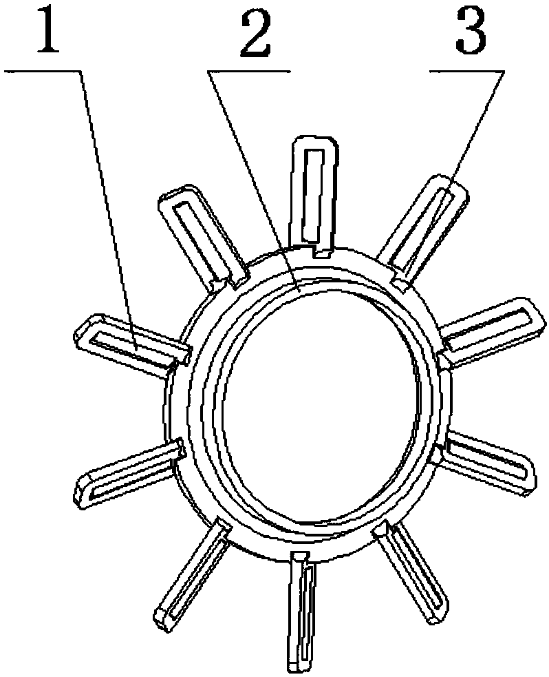
[0015] Provide a slanted needle roller assembly, the slanted needle roller assembly mainly includes a needle roller 1, a central ring 2, and a needle roller bracket 3; the central ring and the needle roller bracket form a petal-shaped structure, and each needle roller bracket is relatively The planes of the rings are all twisted at the same angle, and the needle rollers are supported on the needle roller support for rolling.

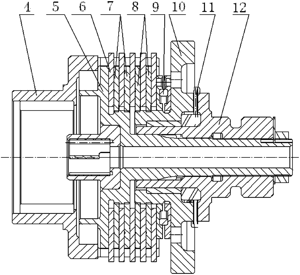
[0016] At the same time, a self-tightening mechanical automatic braking device is provided, which mainly includes a housing 4, a transmission shaft 5, a static friction plate 6, a first dynamic friction plate 7, a second dynamic friction plate 8, a spring 9, and a first gear 10 , the above-mentioned oblique needle roller assembly 11, the second gear 12; the spring 9 is arranged between the second moving friction plate 8 and the first gear 10, and the spring applies a pre-tightening force to the second moving friction plate;

[0017] The inner wall surfac...


PUM


Abstract

The invention relates to a self-tight mechanical automatic brake device used for an electric operation system of a winch. The load problem is solved, and load reverse power direction transmission is stopped. The device comprises a shell, a transmission shaft, a static friction plate, first movable friction plates, second movable friction plates, a spring, a first gear, an inclined roller pin assembly, a second gear and the like. The self-tight mechanical automatic brake device of this type is applied to winches of various types and has the beneficial effects of being compact in structure, high in reliability and the like; the load problem can be effectively solved, and load reverse power flow direction transmission can be stopped; and therefore the self-tight mechanical automatic brake device has quite high economic application value.

Description

technical field [0001] The invention relates to a self-tightening mechanical automatic braking device, which is used for an electric operating system of a winch, which solves the problem of forward load and prevents the load from being transmitted in the reverse power direction. Background technique [0002] At present, the solution to the parallel load of the motor is generally to add sensors and properly control the motor, and the transmission of the load in the direction of reverse power flow is realized through an overrunning clutch; it has the disadvantages of low reliability, large weight and volume, high failure and high cost. Contents of the invention [0003] Technical solutions [0004] Provide a slanted needle roller assembly, the slanted needle roller assembly mainly includes a needle roller 1, a central ring 2, and a needle roller bracket 3; the central ring and the needle roller bracket form a petal-shaped structure, and each needle roller bracket is relative...

Claims


Application Information

Patent Timeline
Patent Type & Authority Patents(China)
IPC IPC(8): F16D55/02F16D65/14
CPCF16D55/02F16D65/14
Inventor 宣源鹏顾卫平李戬
Owner QINGAN GRP
Learn More