Relative Horizontal Displacement Sensor Between Layers of Optical Fiber Bragg Grating for Road

A technology of displacement sensor and optical fiber grating, which is applied in the field of displacement sensor, can solve the problems of inability to measure, affect the service life of the road, and make it difficult to move, and achieve the effects of good anti-electromagnetic interference performance, wide application range, and low optical fiber transmission loss

Active Publication Date: 2019-06-11
HARBIN INST OF TECH
View PDF4 Cites 0 Cited by
  • Summary
  • Abstract
  • Description
  • Claims
  • Application Information

AI Technical Summary

Problems solved by technology

[0003] In some long longitudinal slopes and bus intersections, especially under the action of high temperature in summer and heavy vehicles, the pavement structure often produces interlayer displacement, which can reach 5 or 6 cm in severe cases, which undoubtedly seriously affects the use of roads. life
However, the existing fiber grating displacement sensors can only achieve displacement measurement in a single direction. As the sensor is embedded in the structure, its measurement direction is also fixed, and it is difficult to move under the surrounding pavement materials, making it impossible to carry out Measurement

Method used


Image

  • Relative Horizontal Displacement Sensor Between Layers of Optical Fiber Bragg Grating for Road
  • Relative Horizontal Displacement Sensor Between Layers of Optical Fiber Bragg Grating for Road

Examples


Embodiment Construction

[0019] The present invention will be described in further detail below in conjunction with the accompanying drawings: the present embodiment is implemented on the premise of the technical solution of the present invention, and detailed implementation is provided, but the protection scope of the present invention is not limited to the following embodiments.

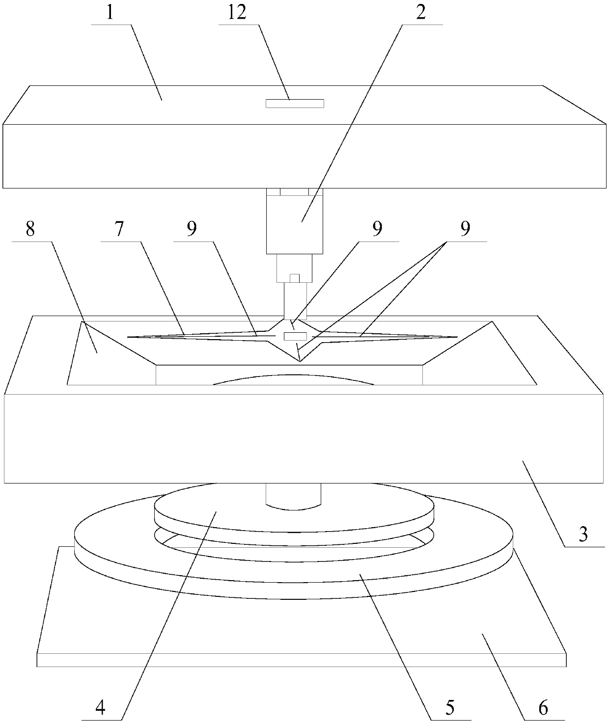
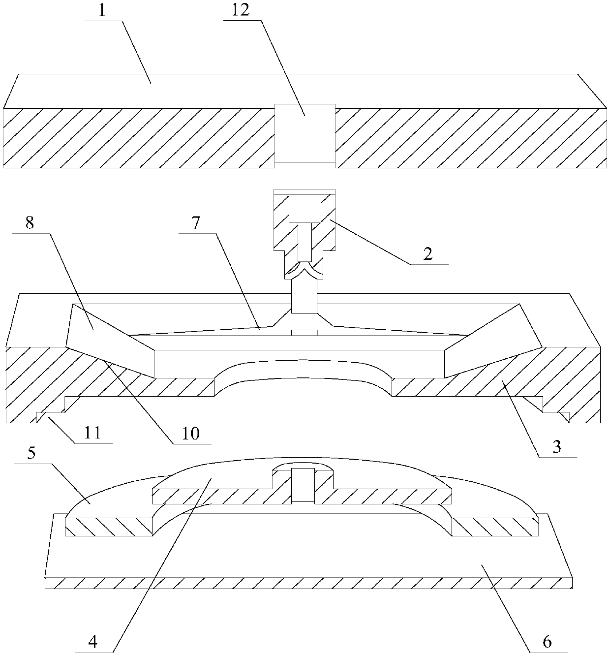
[0020] Such as figure 1 and figure 2 As shown, a relative horizontal displacement sensor between layers of road fiber gratings involved in this embodiment includes: a top cover 1, a central column 2, a bottom plate 3, a fixing ring 4, a silicone pad 5, a fixing plate 6, and equal strength beams 7. Optical fiber grating 9 and glass sheet 10, the bottom of the bottom plate 3 is provided with a fixed plate groove 11, the fixed plate 6 is arranged in the fixed plate groove 11 at the bottom of the bottom plate 3, the upper part of the bottom plate 3 is provided with a chute 8, the chute 8 is provided with a glass sheet 10, th...


PUM


Abstract

The present invention provides a road-use optical fiber grating interlayer relative horizontal displacement sensor. According to the technical scheme of the invention, the test on the relative horizontal displacement between layers inside a pavement structure is realized. A top cover is embedded into the bottom of an upper-layer structure. A center column is connected with a top cover and a uniform strength beam, so that the top cover and the uniform strength beam move together. A bottom plate is embedded into the top of a lower-layer structure, and monitors the mutual displacement condition of the above two layers. A fixed ring is used for fixing the top cover and the bottom plate. Under the fixation of the fixed ring, only a tangential displacement is generated between the top cover and the bottom plate, so that the top cover and the bottom plate are not mutually separated. A silica gel pad is placed between the fixed ring and the bottom plate to limit the rotation of the bottom plate and the top cover, so that the top cover and the bottom plate are rebounded after the displacement. A fixed plate is used for fixing the silica gel pad of and other structures, so that the silica gel pad of and other structures are located inside the bottom plate. The uniform strength beam converts the horizontal sliding generated by the sensor into the vertical displacement. A sliding groove is arranged in the bottom plate and a glass cover plate is covered onto the sliding groove to increase the scratch resistance thereof. An optical fiber grating is stuck onto the uniform strength beam by a special structural adhesive, and the deformation of the uniform strength beam is converted into the wavelength change of the optical fiber grating.

Description

technical field [0001] The invention relates to a relative horizontal displacement sensor between layers of optical fiber gratings for roads, and belongs to the technical field of displacement sensors. Background technique [0002] It is extremely important to grasp the real internal mechanical response of the pavement structure. With the development of optical fiber sensing technology, the fiber grating sensor has the advantages of anti-electromagnetic interference, corrosion resistance, high insulation, wide measurement range, and easy reuse into a network. , It has been widely used in civil engineering, aerospace, petrochemical, electric power, medical, shipbuilding and other fields. When the external force on the fiber Bragg grating changes, the strain distribution of the fiber Bragg grating itself changes accordingly, which causes the change of the center wavelength of the fiber Bragg grating; through the fiber Bragg grating demodulation equipment, the change of the cen...

Claims


Application Information

Patent Timeline
Patent Type & Authority Patents(China)
IPC IPC(8): G01B11/02
CPCG01B11/02
Inventor 董泽蛟张同心马宪永
Owner HARBIN INST OF TECH
Why Eureka
Try Eureka