Ultrasonic guided wave-based pipeline flaw imaging method

A technology of ultrasonic guided wave and imaging method, which is applied in the direction of analyzing solids with sound waves/ultrasonic waves/infrasonic waves, material analysis with sound waves/ultrasonic waves/infrasonic waves, and processing detection response signals. Effects, low image resolution and other problems, to achieve easy understanding and mastery, to overcome the effect of longer guided wave wavelength and high detection sensitivity

Inactive Publication Date: 2017-08-04
SPECIAL EQUIP SAFETY SUPERVISION INSPECTION INST OF JIANGSU PROVINCE +1
View PDF2 Cites 9 Cited by
  • Summary
  • Abstract
  • Description
  • Claims
  • Application Information

AI Technical Summary

Problems solved by technology

The method described in Document 1 needs to design a special delay excitation and receiving system; at the same time, this method needs point-by-point focusing when performing imaging, which is very inefficient
The method described in Document 2 needs to arrange sensors on both sides of the defect for detection. This method needs to know the position of the defect in advance, which has poor practicability and low efficiency in long-distance detection.
[0005] The wavelength of the guided wave detected by the existing ultrasonic guided wave imaging technology is relatively long, which can reach tens of millimeters, the focus of imaging is relatively large, and the resolution of the image is low; Phenomenon, the guided wave components in the pipeline are relatively complex, resulting in poor imaging quality and affecting the detection effect

Method used


Image

  • Ultrasonic guided wave-based pipeline flaw imaging method
  • Ultrasonic guided wave-based pipeline flaw imaging method
  • Ultrasonic guided wave-based pipeline flaw imaging method

Examples


Embodiment Construction

[0040] The present invention will be further described below in conjunction with drawings and embodiments.

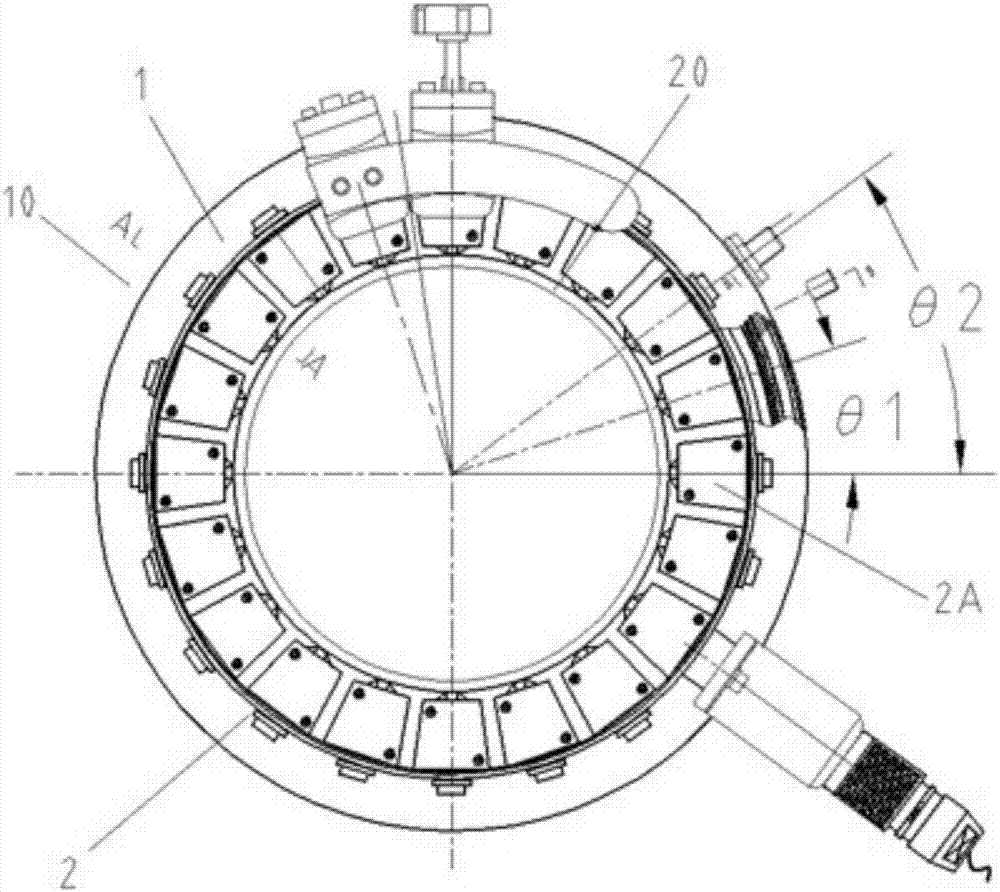
[0041] This embodiment selects a standard pipe 20 with a length of 5.8m, an outer diameter of 108mm, and a material with a wall thickness of 5mm to be a carbon steel pipe 20 as the detection object. Track defect detection.

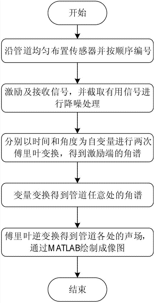
[0042] The imaging method of the present invention comprises the following steps:

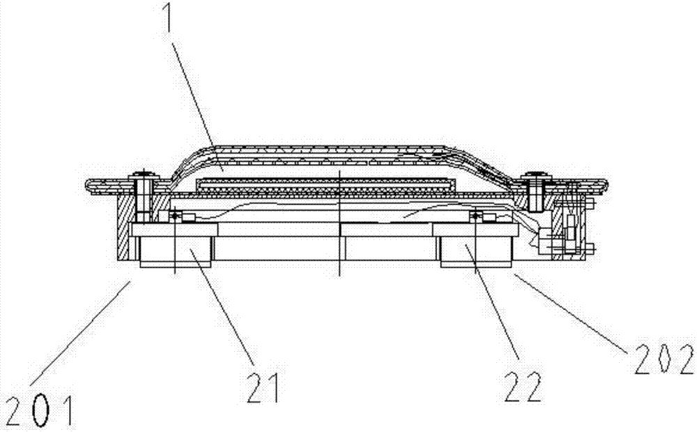
[0043] Such as Figure 1 ~ Figure 4 As shown, 1) the ring fixture 10 is sleeved on one end of the standard pipeline 20 to be checked, (at z=0), and the input end of the ring fixture 10 is connected with a function generator 40 as an excitation source through a signal cable 30 The signal cable 30 at the output end is connected to the power supply 50 , the preamplifier 60 and the input end of the oscilloscope 70 in sequence; the output end of the oscilloscope 70 is connected to the computer 80 through the signal cable 30 . The ring clamp 10 wraps around the circumfere...


PUM


Abstract

The invention discloses an ultrasonic guided wave-based pipeline flaw imaging method, which is used for imaging flaws in a pipeline by using guided wave detection technology. The ultrasonic guided wave-based pipeline flaw imaging method comprises the following steps: under optimal excitation frequency, acquiring detection signals of all receiving sensors, denoising a waveform by using a wavelet filtering technology, and analyzing and calculating detection data by using a Fourier transformation and variable transformation method, so as to obtain data of sound fields at all positions of the pipeline. The invention provides a new research method for detecting pipeline flaws through guided waves with high efficiency; the imaging method does not need a focusing system, so that the influence of circumferential guided waves and other modal guided waves can be eliminated, and the long guided wave wavelength and low focused imaging efficiency can be overcome. The specific information of the flaws can be directly obtained from imaging results, no recalculation is needed. The ultrasonic guided wave-based pipeline flaw imaging method is strong in practicability, high in detection sensitivity, and precise for flaw positioning, and has wide application prospects in the field of nondestructive testing of pipelines.

Description

technical field [0001] The invention relates to a method for non-destructive testing of pipelines, in particular to a defect imaging method for testing pipelines using ultrasonic guided waves. It belongs to the technical field of nondestructive testing. Background technique [0002] Pipelines must be regularly inspected and measures taken in time to prevent pipeline leakage and eliminate safety accidents such as explosions caused by severe leakage. Ultrasonic guided wave pipeline inspection technology has the characteristics of long detection distance and high efficiency, which is very suitable for pipeline inspection with long mileage. However, the results obtained by the existing guided wave inspection are relatively abstract, and the defect information cannot be obtained intuitively. If the guided wave technology can be used to perform imaging inspection on the pipeline, then the inspection results can be visually presented in images, and it is easier for inspectors to u...

Claims


Application Information

Patent Timeline
Patent Type & Authority Applications(China)
IPC IPC(8): G01N29/06G01N29/46
CPCG01N29/069G01N29/46G01N2291/0289G01N2291/044G01N2291/262
Inventor 窦林彬姜银方严有琪陈志伟陈凯歌毛亚东雷玉兰张新匡泓锦蒋俊俊陈波
Owner SPECIAL EQUIP SAFETY SUPERVISION INSPECTION INST OF JIANGSU PROVINCE
Why Eureka
Try Eureka