Transparent excitation source implementation method applied to finite-difference time-domain method

A technology of finite difference in time domain and implementation method, which is applied in the field of computational electromagnetics and can solve problems such as reducing computational efficiency

Active Publication Date: 2017-08-04
UNIV OF ELECTRONIC SCI & TECH OF CHINA
View PDF7 Cites 4 Cited by
  • Summary
  • Abstract
  • Description
  • Claims
  • Application Information

AI Technical Summary

Problems solved by technology

[0018] The disadvantage of this method is that it uses an auxiliary calculation, which reduces the calculation efficiency.

Method used


Image

  • Transparent excitation source implementation method applied to finite-difference time-domain method
  • Transparent excitation source implementation method applied to finite-difference time-domain method
  • Transparent excitation source implementation method applied to finite-difference time-domain method

Examples


Embodiment Construction

[0130] The present invention will be described in further detail below in conjunction with the accompanying drawings and embodiments.

[0131] In the example, the model of two two-dimensional uniform waveguides scattering at the junction is tested, such as Figure 5 shown. The width of the first waveguide is a=22.86mm, the width of the second waveguide is a / 2, the simulation parameters are: space step Δx=Δz=1.143mm, Δt=0.0019ns, simulation time step nt=900. Incentives employ a TE 10 A cosine-modulated Gaussian pulse of the mode, center frequency f 0 =16GHz, the excitation source is loaded on the input port of the first waveguide, and the equation of the excitation source added is

[0132]

[0133] Among them, n 0 =450,n d =125.

[0134] step 1,

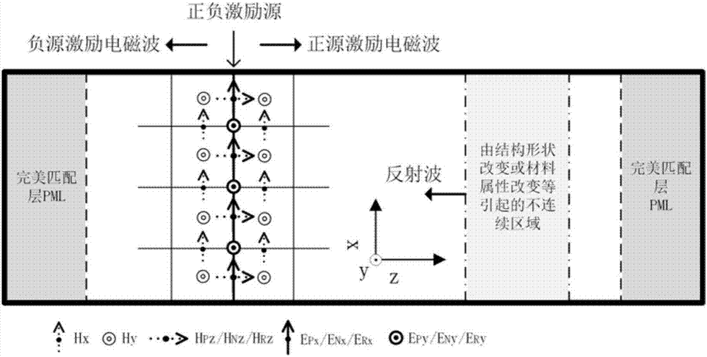
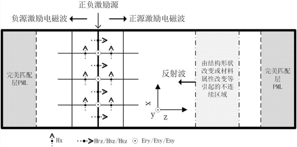
[0135] All electromagnetic field components distributed at the excitation source grid have three sets of values, E Py 、H Pz ,E Ny 、H Nz and E Ry 、H Rz .

[0136] Step 2. According to the excitation source equation f ...


PUM


Abstract

The invention belongs to the technical field of computational electromagnetics, and particularly relates to a transparent excitation source implementation method applied to the finite-difference time-domain method. A Yee network is used, two electric field excitation sources are added to an excitation source grid, and a feedback electric field is reduced, so that the excitation sources are equivalent to hard sources and transparent. Perfectly matched layer absorbing boundary truncated waveguide structures are added in an input port and an output port to be suitable for first-dimensional, second-dimensional and third-dimensional structures. According to the method, extra computation needs to be conducted only on electromagnetic field components on the surfaces of the excitation sources, compared with other methods, the required auxiliary calculation amount is very small, and influences on calculation efficiency can be ignored. The method is transparent, time for auxiliary calculation is avoided for waveguide type calculation simulation problems, an incident field and a scattering field are efficiently obtained, and the method has a good effect on improving the simulation calculation efficiency.

Description

technical field [0001] The invention belongs to the technical field of computational electromagnetics. When using the finite difference time domain method to simulate and calculate the electromagnetic wave characteristics of waveguide structures, it involves a transparent excitation source loaded on the waveguide port, specifically a method for realizing the transparent excitation source applied to the finite difference time domain method. Background technique [0002] In the process of simulation calculation using the finite difference time domain method, it is necessary to add an excitation source to excite electromagnetic waves of a specific frequency band and amplitude, and then obtain the electromagnetic wave transmission characteristics and electromagnetic field distribution of the simulation calculation structure. [0003] Using a non-transparent excitation source to excite electromagnetic waves, in the process of electromagnetic wave propagation, when encountering no...

Claims


Application Information

Patent Timeline
IPC IPC(8): G06F17/50
CPCG06F30/23
Inventor 金晓林谷晓梁黄桃李斌
Owner UNIV OF ELECTRONIC SCI & TECH OF CHINA
Why Eureka
Try Eureka