Supercharge Your Innovation With Domain-Expert AI Agents!

Electric connector

A technology for electrical connectors and housings, applied in the field of electrical connectors, can solve the problems of large installation area of ​​printed circuit boards, shorten the life of the lower shell 93, etc., and achieve the effects of prolonging life and suppressing deterioration

Active Publication Date: 2017-08-04
JST MFG CO LTD
View PDF14 Cites 0 Cited by
  • Summary
  • Abstract
  • Description
  • Claims
  • Application Information

AI Technical Summary

Problems solved by technology

[0030] However, refer to Figure 12 or Figure 13 and Figure 15 , in the electrical connector 9 of the prior art, since the semi-cylindrical bosses 91b, 91b are bulged from both sides of the outer housing 91, there is a problem that the occupied mounting area on the printed circuit board is large
Therefore, there is a problem that these protrusions are worn to shorten the life of the lower shell 93

Method used


Image

  • Electric connector
  • Electric connector
  • Electric connector

Examples


no. 1 approach

[0074] (Structure of electrical connector)

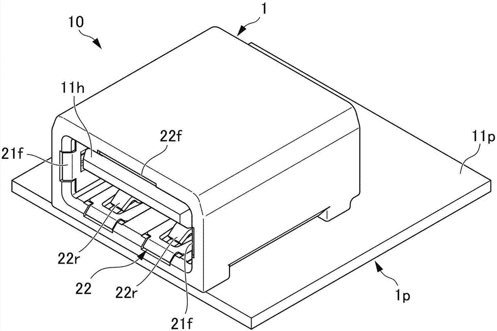
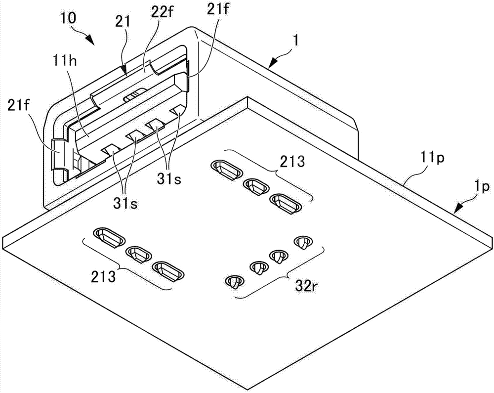
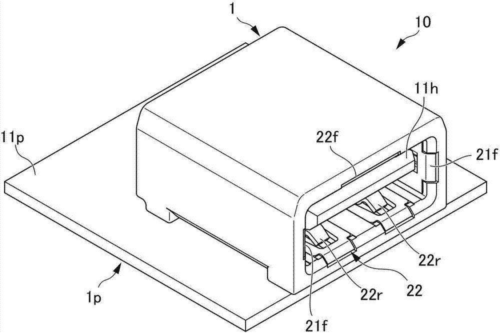
[0075] First, the structure of the electrical connector according to the first embodiment of the present invention will be described. Figure 1A and Figure 1B is a perspective view showing the structure of the electrical connector according to the first embodiment of the present invention, Figure 1A is a state diagram of an electrical connector viewed from above, Figure 1B is a state diagram of an electrical connector viewed from below.

[0076] Figure 2A and Figure 2B is a perspective view showing the structure of the electrical connector of the first embodiment, Figure 2A is a state diagram of an electrical connector viewed from above, Figure 2B is a state diagram of an electrical connector viewed from below.

[0077] Figure 3A-3F is a diagram showing the structure of the electrical connector of the first embodiment, Figure 3A is the front view of the electrical connector, Figure 3B is the top view of the elect...


PUM


Abstract

The invention provides an electric connector that is made compact. A connector 10 comprises a housing 1 and a shell main body 21. The connector 10 also comprises a bottom plate 22 and a plurality of contacts 3. The housing 1 includes a housing chamber 11 in an inner part. The shell main body 21 includes an upper surface plate 21t and a pair of side surface plates 21s and 21s. The shell main body 21 opens in a rectangle shape for freely inserting thereinto a mating electric connector. The bottom plate 22 is arranged so as to be opposite to the upper surface plate 21t. The contact 3 is arranged to a header 11h provided on the housing 1. The shell main body 21 includes a plurality of leg pieces 213 and 213 projected from a pair of side surface plates 21s and 21s The leg pieces 213 and 213 are arranged over a back surface side from the opening side of the shell main body 21. The plurality of leg pieces 213 and 213 are projected from the pair of side surface plates 21s and 21s through a Z flexure part 21z.

Description

technical field [0001] The present invention relates to electrical connectors. In particular, it relates to a structure of an electrical connector in which a shell made of a metal plate that shields electromagnetic waves is disposed inside the housing of the electrical connector, the electrical connector can reduce the mounting area occupied on the printed circuit board, and can be relatively Perform multiple plugging and unplugging of the electrical connector on the opposite side. Background technique [0002] USB (universal serial bus: Universal Serial Bus) is known as one of the specifications of a data transmission path for electrically connecting a computer main body and peripheral devices such as a keyboard, a mouse, and a modem. [0003] In recent years, USB ports are installed in automobiles to charge batteries installed in mobile phones and the like. By mounting the mobile phone on a cradle (cradle) as a charger, and connecting the USB connector (plug) provided on...

Claims


Application Information

Patent Timeline
IPC IPC(8): H01R12/71H01R12/51H01R13/46H01R13/6585
CPCH01R12/51H01R12/71H01R13/46H01R13/6585
Inventor 宫本大智细山田刚
Owner JST MFG CO LTD
Features
  • R&D
  • Intellectual Property
  • Life Sciences
  • Materials
  • Tech Scout
  • Unparalleled Data Quality
  • Higher Quality Content
  • 60% Fewer Hallucinations
Learn More