
Arranged magnetic steel supporting device for rotor of permanent magnet motor

A technology for permanent magnet motors and supporting devices, which is applied in the direction of electromechanical devices, manufacturing motor generators, manufacturing stator/rotor bodies, etc., can solve the problems of permanent magnet motors, etc., and achieve the effects of reducing labor rates, simple structure, and cost saving

Active Publication Date: 2017-08-04
ANHUI ANKAI AUTOMOBILE
View PDF5 Cites 3 Cited by
  • Summary
  • Abstract
  • Description
  • Claims
  • Application Information

AI Technical Summary

Problems solved by technology

[0004] The object of the present invention is to provide a magnetic steel supporting device for permanent magnet motor rotors. There is no special device to support the rotor in the production process of permanent magnet motors, which greatly reduces the labor intensity of motor production and improves the safety of production

Method used


Image

  • Arranged magnetic steel supporting device for rotor of permanent magnet motor
  • Arranged magnetic steel supporting device for rotor of permanent magnet motor
  • Arranged magnetic steel supporting device for rotor of permanent magnet motor

Examples


Embodiment Construction

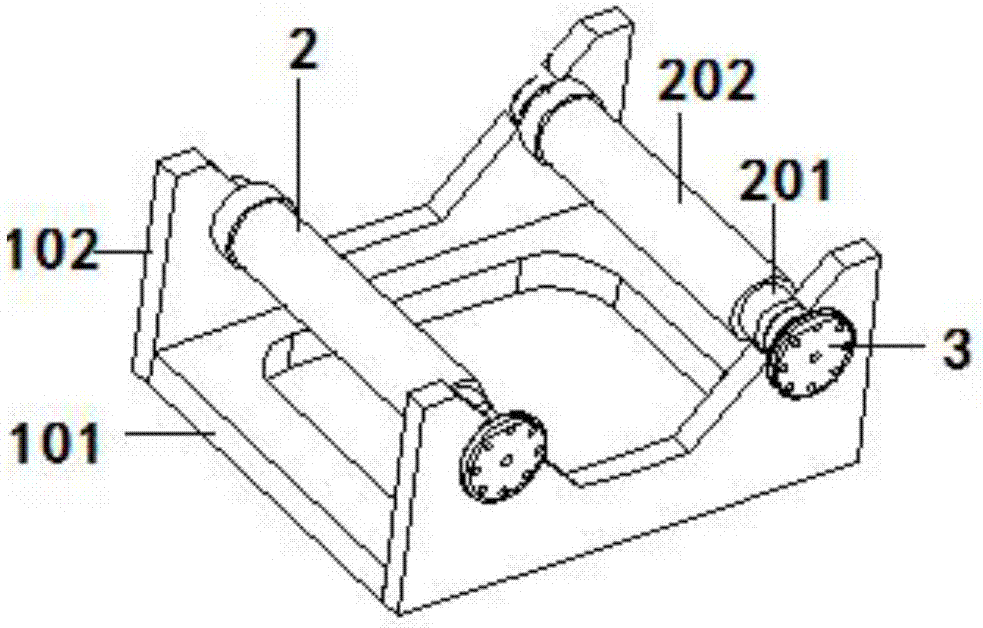
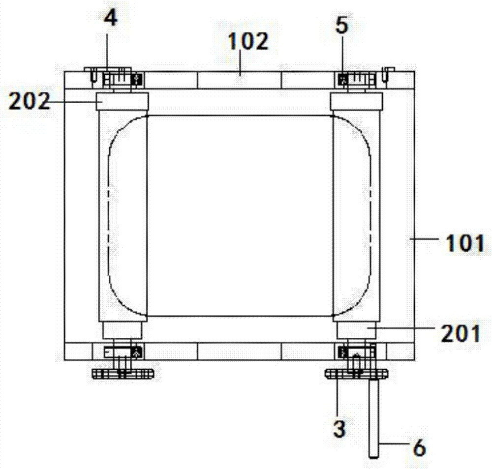
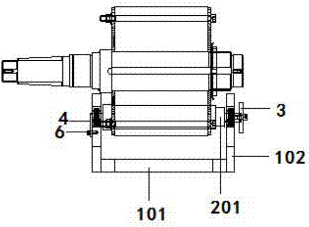
[0033] A mounting magnet support device for a permanent magnet motor rotor, such as figure 1 , figure 2 , image 3 , Figure 4 As shown, including positioning support 1, rolling shaft 2 and brake pin 6;

[0034] Such as Figure 5 As shown, the positioning support 1 includes a base 101 and two opposite supports 102 fixed on the two ends of the base 101, the two supports 102 are fixed on the two ends of the base 101 by screws, and the surface of the base 101 has a square Through holes, the support 102 is provided with an inverted trapezoidal groove that does not penetrate the bottom edge along the top edge, and two arc-shaped grooves 103 are symmetrically opened on the side wall of the inverted trapezoidal groove, and the rolling shaft 2 is installed in the arc-shaped groove 103. The opening of the arc-shaped groove 103 is perpendicular to the side wall of the inverted trapezoidal groove, and the side wall of the support 102 has a positioning groove, and the side wall of th...


PUM


Abstract

The present invention discloses an arranged magnetic steel supporting device for the rotor of a permanent magnet motor. The device comprises a positioning support, rolling shafts and a brake pin. The positioning support comprises a base and two opposite bearers fixedly arranged at the two ends of the base. Along the top edge of each bearer, the bearer is provided with an inverted trapezoidal groove configured not to pass through the bottom edge of the bearer. The sidewall of the inverted trapezoidal groove is symmetrically provided with two arc-shaped grooves and rolling shafts are arranged in the arc-shaped grooves. The sidewall of each bearer is provided with a positioning groove and a limiting plate is fixed on the sidewall of the bearer. Each rolling shaft comprises a rotating shaft and an aluminum sleeve sleeved onto the outer surface of the sidewall of the rotating shaft. Bearings are arranged at the two ends of each rotating shaft. One end of each rotating shaft is connected with the limiting plate, and the other end of the rotating shaft is fixedly connected with a limiting circular disc. The limiting circular disc is fixed onto the sidewalls of the bearers through the brake pin. The device is simple in structure and strong in practicality. The problem in the prior art that no special device used for supporting the rotor of an existing permanent magnet motor is available during the production process of the permanent magnet motor can be solved. Meanwhile, the labor intensity of the motor production is greatly relieved, and the production safety is improved.

Description

technical field [0001] The invention belongs to the technical field of permanent magnet motor production, and relates to a magnetic steel supporting device for a rotor of a permanent magnet motor. Background technique [0002] In recent years, with the increasing emphasis on the environment, the country's emphasis on new energy has become more and more important, and there are more and more new energy vehicles on the market. Therefore, the permanent magnet motor, the motor of new energy vehicles, is becoming more and more important to improve production efficiency and reduce the labor intensity of production employees in the production process. It is an important guarantee to increase the production output of permanent magnet motors. [0003] Therefore, in the production process of the permanent magnet motor, in the process of manufacturing the rotor of the permanent magnet motor, a tool with a simple structure and easy to use is needed. Contents of the invention [0004...

Claims


Application Information

Patent Timeline
IPC IPC(8): H02K15/03
CPCH02K15/03
Inventor 许久段瑞峰张璨璨王林照张海庆张伟明
Owner ANHUI ANKAI AUTOMOBILE
Learn More