Diaphragm and micro sound generator provided with the same

A pattern and arc-shaped technology, applied in the field of micro-sounders, can solve the problems of low sensitivity of micro-sounders, easy wrinkles at the four corners, and high harmonic distortion, so as to improve the reliability margin and have a large reliability margin , the effect of small high-order harmonic distortion

Active Publication Date: 2019-12-13
GOERTEK INC
View PDF4 Cites 0 Cited by
  • Summary
  • Abstract
  • Description
  • Claims
  • Application Information

AI Technical Summary

Problems solved by technology

[0004] 1. When the diaphragm vibrates at a large displacement, it will vibrate, the vibration is not stable, and noise is easy to appear;
[0005] 2. The compliance of the diaphragm is low, resulting in low sensitivity and poor acoustic performance of the miniature sound generator;
[0006] 3. Wrinkles tend to appear at the four corners of the diaphragm when it vibrates, resulting in higher harmonic distortion. At the same time, it will also make the ring part of the diaphragm fatigue, making it difficult to pass the reliability test.

Method used


Image

  • Diaphragm and micro sound generator provided with the same
  • Diaphragm and micro sound generator provided with the same
  • Diaphragm and micro sound generator provided with the same

Examples


Embodiment 1

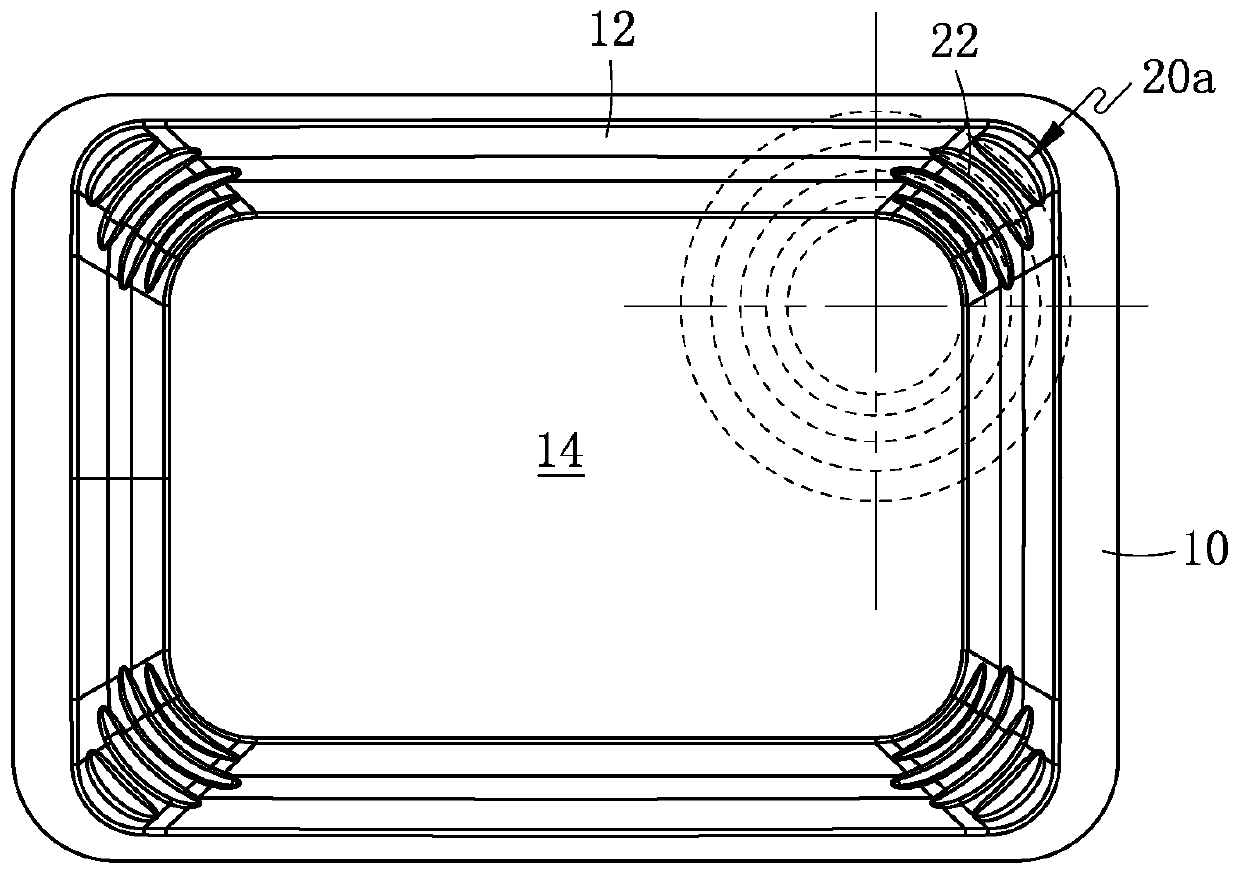
[0037] Such as figure 1 and figure 2 Commonly shown, a diaphragm includes a central part 14 , a ring part 12 and a fixed part 10 which are sequentially connected as one from the inside to the outside. The ring portion 12 includes an arc corner and a first side and a second side connected by the arc corner. Patterns 20a are distributed on the arc-shaped corners of the ring part 12. In the orthographic projection plane of the diaphragm, the patterns 20a include at least one curved pattern 22, and each curved pattern 22 is composed of adjacent The first side extends toward the second side, that is, each curved pattern 22 extends from one end of the arc-shaped corner to the other end. The curved patterns 22 at each arc-shaped corner are arranged sequentially from the inside to the outside of the arc-shaped corner. In this embodiment, it is preferable that the convex curve direction of the curved pattern 22 is consistent with the convex curve direction of the arc-shaped corner....

Embodiment 2

[0048] This embodiment is basically the same as Embodiment 1, the difference is that:

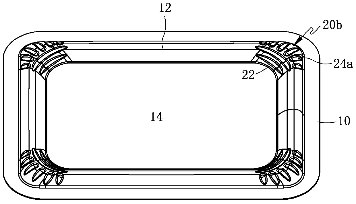
[0049] Such as image 3 and Figure 4 Commonly shown, the arc-shaped corners of the ring portion 12 are distributed with patterns 20b, and the pattern 20b includes a plurality of curved patterns 22 distributed on the inside of the arc-shaped corners of the ring portion 12 and the arc-shaped corners distributed on the ring portion 12 At least one linear pattern 24a on the outer side of the In practical applications, the curved pattern 22 may also be arranged on the outside of the arc-shaped corner, and the linear pattern 24a may be arranged on the inside of the arc-shaped corner.

[0050] Such as image 3 and Figure 4 As shown together, in this embodiment, there are two curved patterns 22 and six linear patterns 24a. In the orthographic projection plane of the diaphragm, six linear patterns 24a are distributed radially from the inner side to the outer side of the arc-shaped corner. Th...

Embodiment 3

[0056] This embodiment is basically the same as Embodiment 1, the difference is that:

[0057] Such as Figure 5 and Figure 6 Commonly shown, the arc-shaped corner of the ring portion 12 is distributed with a pattern 20c, and the pattern 20c includes a curved pattern 22 distributed on the inside of the arc-shaped corner of the ring portion 12 and at least one straight line pattern distributed on the outside of the arc-shaped corner. pattern. In practical applications, the curved pattern 22 may also be arranged on the outer side of the arc-shaped corner, and the linear pattern 24b may be arranged on the inner side of the arc-shaped corner.

[0058] Such as Figure 5 and Figure 6 As shown together, in this embodiment, there are two curved patterns 22 and three linear patterns 24b. In the orthographic projection plane of the diaphragm, three linear patterns 24 b are radially distributed from the outer edge of the ring portion 12 to the curved pattern 22 . The lengths of t...


PUM


Abstract

Disclosed are a vibrating diaphragm and a miniature sound generator provided with the vibrating diaphragm, relating to the technical field of electroacoustic products. The vibrating diaphragm comprises a central portion, an edge portion and a fixed portion connected from inside to outside in sequence, wherein the edge portion comprises arc-shaped corners, and a first side and a second side connected by the arc-shaped corners; patterns are distributed on the arc-shaped corners; in an orthographic projection plane of the vibrating diaphragm, the patterns comprise at least one curve-shaped pattern; each curve-shaped pattern extends from the adjacent first side of the edge portion to the second side; and the curve-shaped patterns on each of the arc-shaped corners are arranged from an inner side to an outer side of the arc-shaped corner in sequence. According to the vibrating diaphragm and the miniature sound generator provided with the vibrating diaphragm, the vibrating diaphragm vibrates stably, the compliance is high, wrinkles will not easily be generated, and the anti-fatigue capability is strong, so that the miniature sound generator has high sensitivity, small distortion, high sound quality and a high reliability margin.

Description

technical field [0001] The invention relates to the technical field of electroacoustic products, in particular to a vibrating membrane and a miniature sound generator provided with the vibrating membrane. Background technique [0002] Miniature sound generator is an important acoustic component in portable electronic equipment, which is used to convert sound wave electric signal into sound signal, and is an energy conversion device. The micro sounder usually includes a vibration system and a magnetic circuit system. The vibration system includes a diaphragm and a voice coil combined together. The diaphragm includes a central part, a ring part and a fixed part that are sequentially combined from the inside to the outside. Important components play a vital role in the sound reproduction performance of the micro-sounder, which determines the conversion quality of the micro-sounder from electrical energy to sound energy. [0003] The pattern of the surround part of the existing...

Claims


Application Information

Patent Timeline
Patent Type & Authority Patents(China)
IPC IPC(8): H04R7/04H04R9/06H04R9/02
CPCH04R7/04H04R9/02H04R9/06H04R2207/021H04R2400/11
Inventor 李柯何超锋宋健赵国栋
Owner GOERTEK INC
Why Eureka
Try Eureka