
Solar vacuum flat plate collector

A flat plate collector and solar energy technology, applied in the field of solar energy applications, can solve the problems of restricting the maximum heat collection temperature of the collector, limiting the use of the flat plate collector, etc., to achieve the effect of expanding the use and stabilizing industrial energy.

Inactive Publication Date: 2017-08-08
余华阳
View PDF5 Cites 1 Cited by
  • Summary
  • Abstract
  • Description
  • Claims
  • Application Information

AI Technical Summary

Problems solved by technology

[0002] The existing solar flat panel heat collector has only one layer of glass on the surface of the plate core, and the space between the glass and the plate core is filled with air, which is a layer of air layer. Because the air in the air layer is heated to generate convection, the heat energy absorbed by the plate core is continuously transferred to With glass, the heat is continuously dissipated in the atmosphere along the glass surface. The larger the heat-absorbing surface, the larger the heat-dissipating surface. The higher the temperature of the plate core, the more heat dissipation, which seriously restricts the maximum collector The hot temperature prevents the flat plate collector from producing steam to enter the industrial application field, and becomes an industrial energy source. It can only produce hot water and can only be used in the low temperature field, which greatly limits the use of the flat plate collector. Therefore, it needs to be improved.

Method used


Image

  • Solar vacuum flat plate collector

Examples


Embodiment Construction

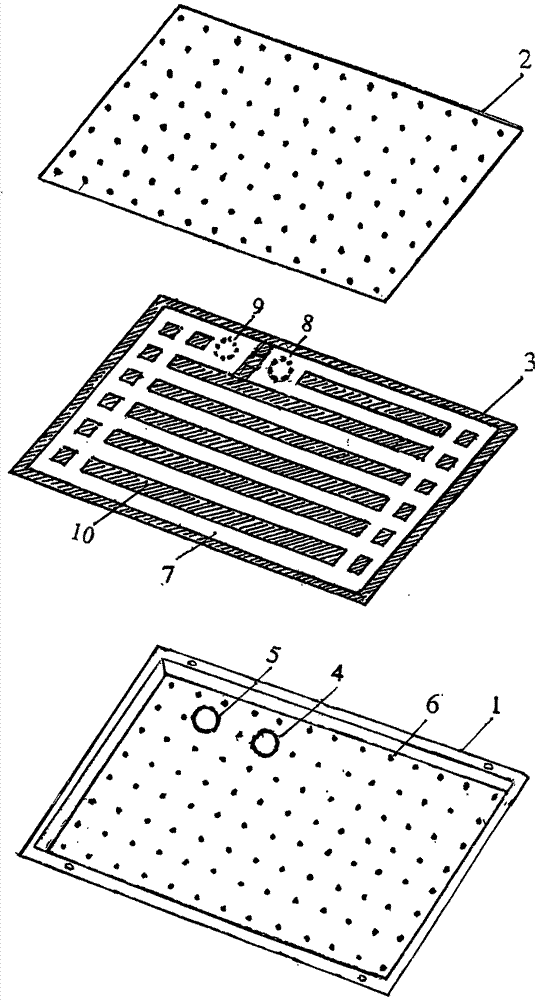
[0013] The specific embodiment of the present invention is described below in conjunction with accompanying drawing, solar vacuum flat plate heat collector comprises insulation box and heat-absorbing plate core, and heat-absorbing plate core 3 is arranged in the middle of heat-insulating box; Described heat-retaining box comprises box body 1 and lid 2 , the box body 1 and the box cover 2 are all made of glass; the bottom surface of the box body 1 has a number of point-like protrusions 6 with equal spacing along the horizontal direction, these point-like protrusions become the support columns of the vacuum space, and the bottom surface of the box body 1 also has inlet pipes. Hole 4 and pipe outlet hole 5; Lid 2 is a piece of low-iron ultra-clear flat glass, and its lower surface also has the same point-like protrusion 6 as the bottom surface of box body 1; Described heat-absorbing plate core 3 is made of metal material Production, the heat-absorbing plate core 3 is a heat-absorb...


PUM


Abstract

The invention provides a solar vacuum flat plate collector. The solar vacuum flat plate collector comprises a heat insulation box and an absorber plate core arranged in the heat insulation box, wherein the heat insulation box comprises a box body and a box cover which are both made of glass; a plurality of point-like bulges, a pipe-in hole and a pipe-out hole are formed in the bottom surface of the box body; the box cover is sheet glass, and the same point-like bulges are formed on the lower surface of the box cover; the absorber plate core is made of a metal material, a heat absorption runner is arranged in the absorber plate core, an inlet pipe nozzle is arranged at one end of the runner, an outlet pipe nozzle is arranged at the other end of the runner, the absorber plate core is arranged in the box body, and the inlet pipe nozzle and the outlet pipe nozzle penetrate the pipe-in hole and the pipe-out hole correspondingly; and the box cover is closed to seal a box gap, air in the box body is pumped out, and an air pumping hole is sealed to enable the absorber plate core to be a vacuum heat insulating layer in all directions. Therefore, the working temperature of a heat collector can be higher than 120 DEG C, steam of 100 DEG C or above can be produced, and the heat collector and an electric steam boiler can complement for each other to enable solar energy to become a stable industrial energy, and application of the flat plate collector is greatly expanded.

Description

technical field [0001] The invention belongs to the field of solar energy application, in particular to a solar vacuum flat plate heat collector. Background technique [0002] The existing solar flat panel heat collector has only one layer of glass on the surface of the plate core, and the space between the glass and the plate core is filled with air, which is a layer of air layer. Because the air in the air layer is heated to generate convection, the heat energy absorbed by the plate core is continuously transferred to With glass, the heat is continuously dissipated in the atmosphere along the glass surface. The larger the heat-absorbing surface, the larger the heat-dissipating surface. The higher the temperature of the plate core, the more heat dissipation, which seriously restricts the maximum collector The hot temperature prevents the flat plate heat collector from producing steam to enter the industrial application field and becomes an industrial energy source. It can o...

Claims


Application Information

Patent Timeline
IPC IPC(8): F24J2/05F24J2/26F24J2/48F24J2/51F24J2/46F24S10/40F24S10/75
CPCF24S10/40F24S40/10F24S70/12F24S70/20F24S70/30F24S80/65Y02E10/44Y02P80/20
Inventor 余华阳
Owner 余华阳
Learn More