A miniaturized non-radioactive electron source with controllable emission current

A current emission and radioactivity technology, applied in the field of miniaturized non-radioactive electron sources, can solve problems such as complex structure, small electron kinetic energy, and inability to change ionization parameters

Active Publication Date: 2018-12-14
安徽恒慧仪表有限公司
View PDF4 Cites 0 Cited by
  • Summary
  • Abstract
  • Description
  • Claims
  • Application Information

AI Technical Summary

Problems solved by technology

[0002] The disadvantages of the commonly used radioactive β-decay electron sources are: the ionization parameters cannot be changed, such as ionization time, electron kinetic energy, electron current, density, etc., and in many applications, the use of radioactive sources is not allowed. Especially in terms of electron focusing, the disadvantages of existing non-radioactive electron sources are: complex structure, excessive volume of electron focusing system, including an electrostatic lens system and a magnetic electron beam guiding device, both of which require a considerable vacuum cavity, in addition, the electrostatic lens system operates at high potentials and requires complex electronics
In addition, some existing non-radioactive electron sources cannot achieve the same performance as radioactive electron sources, especially the kinetic energy of the emitted electrons is small

Method used


Image

  • A miniaturized non-radioactive electron source with controllable emission current

Examples


Embodiment Construction

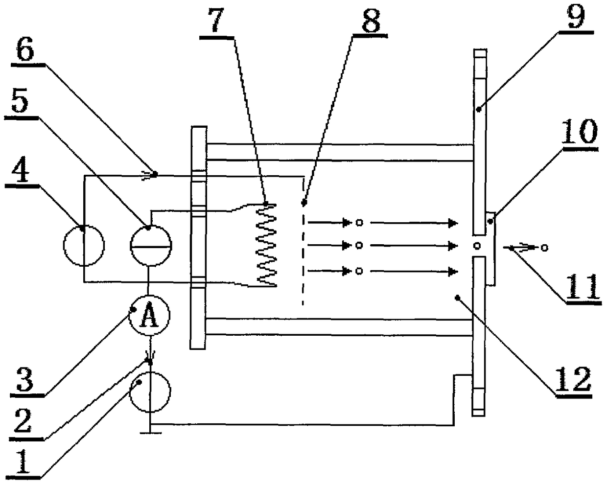
[0013] Such as figure 1 It is a schematic diagram of the present invention, including accelerating voltage source 1, electron emission current 2, ammeter 3, extracting voltage source 4, filament heating current source 5, extracting grid current 6, filament 7, extracting grid 8, accelerating electrode 9, nitriding Silicon film 10, electron current 11 in atmospheric environment, vacuum chamber 12, electron source works in pulse mode, described filament 7 is positioned at one end in vacuum chamber 12, and the other end of vacuum chamber 12 is described accelerating electrode 9, described accelerating There is an opening in the center of the electrode 9, and the silicon nitride film 10 is covered and closely attached to the central opening of the accelerating electrode 9 outside the vacuum chamber 12. Air will not pass through the silicon nitride film 10 and will not affect The vacuum environment in the vacuum chamber 12, the accelerating voltage source 1 generates a potential dif...


PUM


Abstract

The invention relates to the technical field of vacuum electronics, and provides a miniaturized non-radioactive electron source with a controllable emission current. The miniaturized non-radioactive electron source mainly comprises an acceleration voltage source, an ampere meter, an extraction voltage source, a filament heating current source, filaments, an extraction grid, an acceleration electrode, a silicon nitride film and a vacuum cavity, wherein the extraction grid is positioned in a position in front of the filaments, having a distance of 1mm from the filaments, in the vacuum cavity; the acceleration electrode is arranged at the other end of the vacuum cavity; the silicon nitride film is attached to a central opening of the acceleration electrode outside the vacuum cavity; by virtue of the acceleration voltage source, electrons emitted from the filaments are accelerated to obtain kinetic energy; by adjusting the extraction voltage source, focusing or defocusing of the electron beams in the vacuum cavity can be controlled; the space between the extraction grid and the acceleration electrode is an acceleration region with a length of 5mm; the current can reach 0-300mA when the filaments are in use; an electron extraction electric field between the filaments and the extraction grid is independent from an acceleration electric field, so that electron emission can be controlled by adjusting the current of the filaments and the extraction electric field; and the silicon nitride film is 1*1mm<2> in area and 250nm in thickness.

Description

technical field [0001] The invention relates to the technical field of vacuum electronics, in particular to a miniaturized non-radioactive electron source with simple design and effective operation with controllable emission current. Background technique [0002] The disadvantages of the commonly used radioactive β-decay electron sources are: the ionization parameters cannot be changed, such as ionization time, electron kinetic energy, electron current, density, etc., and in many applications, the use of radioactive sources is not allowed. Especially in terms of electron focusing, the disadvantages of existing non-radioactive electron sources are: complex structure, excessive volume of electron focusing system, including an electrostatic lens system and a magnetic electron beam guiding device, both of which require a considerable vacuum cavities, and electrostatic lens systems operate at high potentials, requiring sophisticated electronics. In addition, some existing non-ra...

Claims


Application Information

Patent Timeline
Patent Type & Authority Patents(China)
IPC IPC(8): H01J37/06H01J37/075H01J37/073
CPCH01J37/06H01J37/073H01J37/075
Inventor 赵永建张向平傅晶晶
Owner 安徽恒慧仪表有限公司
Why Eureka
Try Eureka