Method for forming motor stator

A motor stator and stator tooth technology, which is applied in the manufacture of motor generators, stator/rotor bodies, electrical components, etc., can solve the problems of increased reluctance and winding difficulties, and achieve the effect of fast winding

Inactive Publication Date: 2017-08-08
JOHNSON ELECTRIC SHENZHEN
View PDF0 Cites 1 Cited by
  • Summary
  • Abstract
  • Description
  • Claims
  • Application Information

AI Technical Summary

Problems solved by technology

However, if the notch is too large, the reluctance between the position where the stator core is provided with the notch and the rotor permanent magnet will increase; if the notch is too small, it will make winding difficult

Method used


Image

  • Method for forming motor stator
  • Method for forming motor stator
  • Method for forming motor stator

Examples


Embodiment Construction

[0027] The following will clearly and completely describe the technical solutions in the embodiments of the present invention with reference to the accompanying drawings in the embodiments of the present invention. Obviously, the described embodiments are only some of the embodiments of the present invention, not all of them. Based on the embodiments of the present invention, all other embodiments obtained by persons of ordinary skill in the art without making creative efforts belong to the protection scope of the present invention.

[0028] It should be noted that when a component is said to be "fixed" to another component, it can be directly on the other component or there can also be an intervening component. When a component is said to be "connected" to another component, it may be directly connected to the other component or there may be intervening components at the same time. When a component is said to be "set on" another component, it may be set directly on the other ...


PUM


Abstract

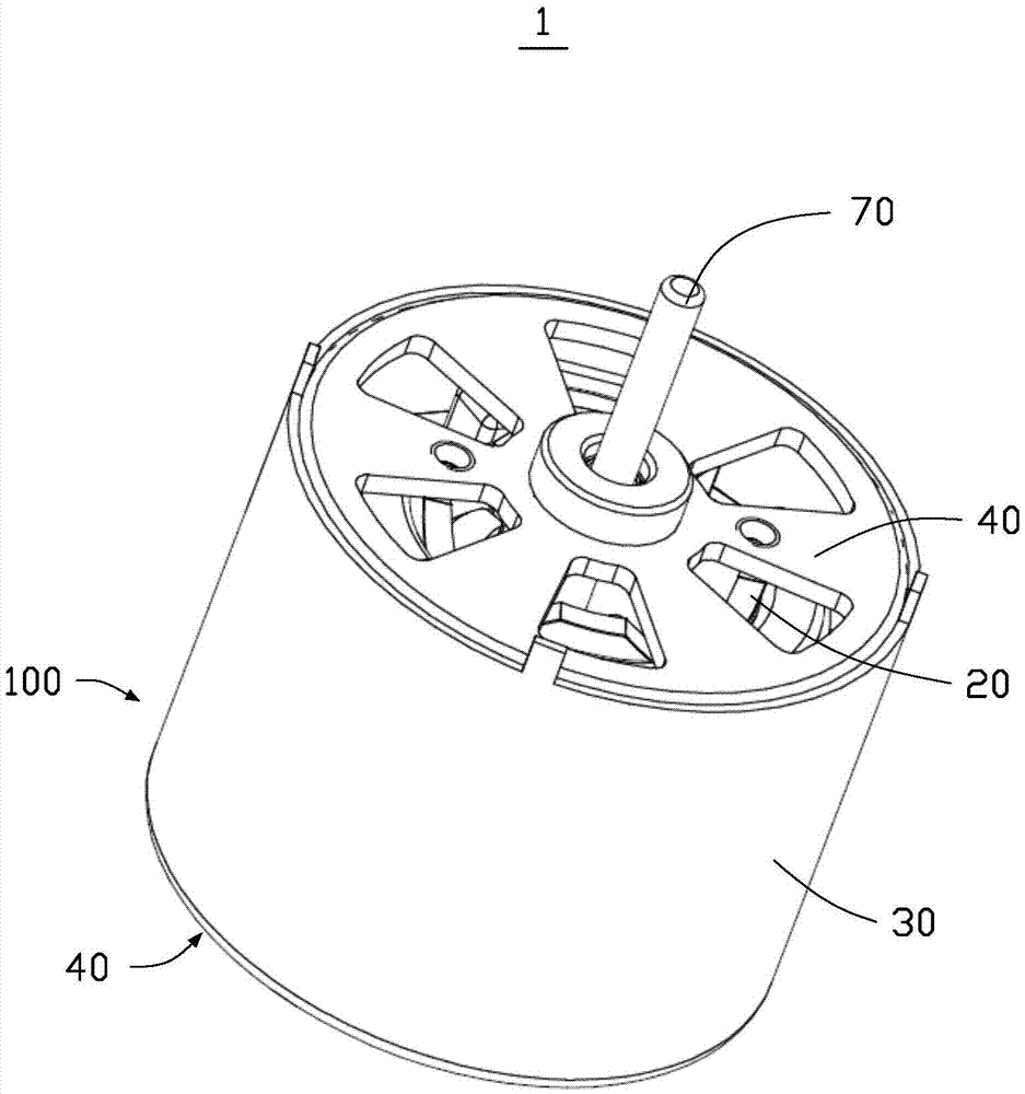
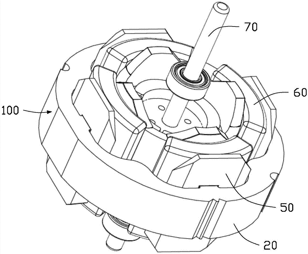
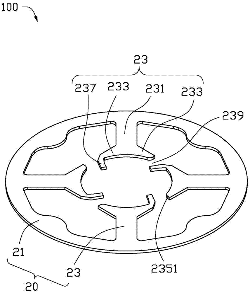
The invention relates to a method for forming a motor stator. The method includes the steps of: a) providing a plurality of plates or metal powder and forming the plates or the metal powder into a plurality of magnetic chips, wherein each magnetic chip comprises a yoke portion and a plurality of stator teeth, each of the stator teeth comprises a tooth portion and two pole shoes, and one end of one of the pole shoes extends towards the direction away from the yoke portion to form a bent portion; b) axially overlapping the plurality of magnetic chips and fixing the magnetic chips to form a stator core; c) providing a bobbin bracket, and mounting the bobbin bracket on the stator core; d) winding wires on the bobbin bracket; and e) bending the bent portions towards the direction opposite to the axial center of the stator core so that the end portions of the bent portions are leveled with the pole shoes of the neighbor stator teeth. The method makes the winding convenient and fast.

Description

technical field [0001] The invention relates to the field of motors, in particular to a method for forming a motor stator. Background technique [0002] The motor generally winds the stator winding on the stator core. After the stator winding is energized, a changing magnetic field is generated, thereby driving the rotor embedded with permanent magnets to rotate. The stator core generally includes an annular yoke and a plurality of teeth extending inward from the yoke, the stator windings are wound on the teeth, and slots are provided between adjacent stator teeth. However, if the notch is too large, the reluctance between the position where the stator core is provided with the notch and the permanent magnet of the rotor will increase; if the notch is too small, winding will be difficult. Contents of the invention [0003] In view of this, the present invention aims to provide a novel stator forming method convenient for winding. [0004] A method for forming a motor sta...

Claims


Application Information

Patent Timeline
Patent Type & Authority Applications(China)
IPC IPC(8): H02K15/02
CPCH02K15/026H02K2213/09H02K1/146H02K15/095H02K3/18H02K15/022
Inventor 李越张涛柴捷周垂友
Owner JOHNSON ELECTRIC SHENZHEN
Why Eureka
Try Eureka