Dynamic root key generating method

A technology for dynamically generating and rooting keys, applied in electrical components, wireless communications, security devices, etc., can solve problems such as key leakage, and achieve the effect of security protection

Inactive Publication Date: 2017-08-08
POTEVIO INFORMATION TECH
View PDF7 Cites 3 Cited by
  • Summary
  • Abstract
  • Description
  • Claims
  • Application Information

AI Technical Summary

Problems solved by technology

[0010] In view of this, the main purpose of the present invention is to provide a method and system for dynamically generating a root key to solve the problem that the root key is easily leaked by storing the root key through software

Method used


Image

  • Dynamic root key generating method
  • Dynamic root key generating method
  • Dynamic root key generating method

Examples


Embodiment 1

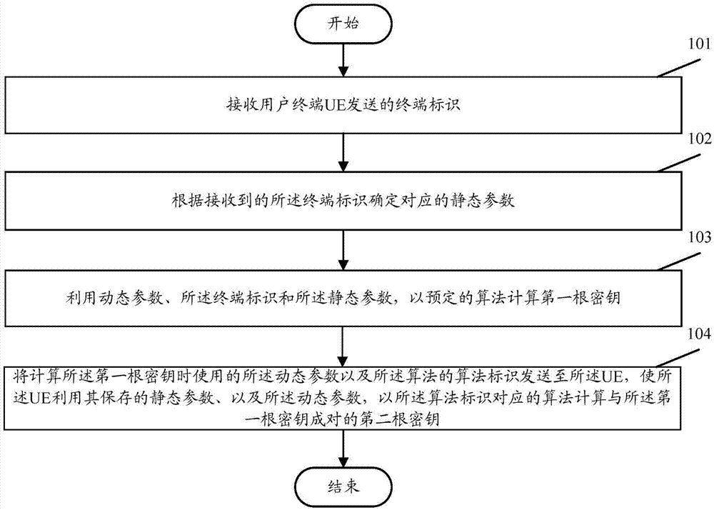
[0034] figure 1 It is a flowchart of an embodiment of the present invention, such as figure 1 As described, this embodiment includes the following steps performed in the core network:

[0035] Step 101: Receive a terminal identifier sent by a user terminal UE.

[0036] In this step, the core network receives the terminal identifier sent by the UE, and the terminal identifier is carried in the request message.

[0037] Wherein, the terminal identifier of the UE can uniquely identify the UE, preferably, an International Mobile Subscriber Identification Number (IMSI) can be used as the terminal identifier of the UE.

[0038] Step 102: Determine corresponding static parameters according to the received terminal identifier.

[0039] In this step, the core network determines the corresponding static parameters according to the received terminal identification of the UE. Specifically, the core network has pre-saved the correspondence table between the terminal identification of th...

Embodiment 2

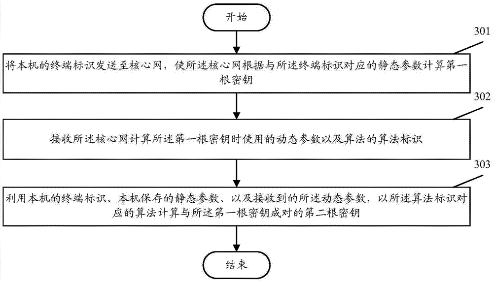
[0050] image 3 is another embodiment of the present invention, such as image 3 As mentioned above, this embodiment includes the following steps performed at the user terminal UE:

[0051] Step 301: Send the terminal identification of the local machine to the core network, so that the core network calculates the first root key according to the static parameters corresponding to the terminal identification.

[0052] In this step, it is embodied in that the UE initiates the authentication and authentication process with the core network, and sends the local terminal identification to the core network, so that the core network calculates the first root key according to the static parameters corresponding to the terminal identification . The steps for the core network to calculate the first root key are detailed in Embodiment 1 and will not be repeated here.

[0053] In actual implementation, the UE may send its own terminal identifier to the core network by carrying its own t...

Embodiment 3

[0063] Figure 4 Be the flow chart of this embodiment, such as Figure 4 shown, including the following steps:

[0064] Step 401: UE sends a request packet carrying its own IMSI to the core network.

[0065] Step 402: The core network receives the request message, and determines the corresponding public key according to the IMSI carried in the request message.

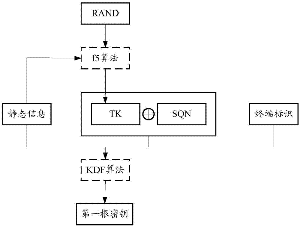
[0066] Step 403: The core network dynamically generates an original random number R1, calculates R1 and IMSI through the f5 algorithm to obtain a random number TK1, and determines another dynamic parameter SQN.

[0067] Step 404: Using TK1, SQN, the received IMSI and the determined public key, calculate the first root key with the KDF algorithm.

[0068] Step 405: Establish its own key system according to the calculated first root key.

[0069] Step 406: Delete the first root key.

[0070] Step 407: Send an acknowledgment message to the UE, the acknowledgment message carrying the algorithm identification S of the ...


PUM


Abstract

The invention discloses a dynamic root key generating method. The method comprises the followings steps, executed in the core network, that a terminal identification is received from UE; a corresponding static parameter is determined according to the received terminal identification; a first root key is calculated in a predetermined algorithm by utilizing a dynamic parameter, the terminal identification and a static parameter; and the dynamic parameter used when the first root key is calculated and an algorithm identification of the algorithm are sent to the UE, so that the UE calculates a second root key paired with the first key in an algorithm corresponding to the algorithm identification by utilizing the stored static parameter, terminal identification and static parameter. According to the invention, the problem of secret key leakage caused by storing the secret key via software is overcome effectively, the safety of root key is protected, and the manual management and maintenance cost of the root key is reduced.

Description

technical field [0001] The invention relates to mobile communication technology, in particular to a method for dynamically generating a root key. Background technique [0002] In terms of security, LTE (Long Term Evolution) adopts two security layers: access layer security and non-access layer security. Its key system fully realizes key isolation, that is, different links and different purposes The keys are independent of each other. For this reason, the system designs the security key level as a more complex multi-layer architecture, that is, the terminal and the core network first calculate two core keys CK and IK through a permanent root key K, and then A temporary key Kasme is produced by the two core keys CK and IK through an algorithm, and finally the secondary dedicated subkey for user data and signaling encryption and integrity protection is derived from the temporary key Kasme. It can be seen that the permanent root key K is located at the top of the spanning tree ...

Claims


Application Information

Patent Timeline
Patent Type & Authority Applications(China)
IPC IPC(8): H04W12/04
CPCH04W12/04
Inventor 蒯澄宇甄景蕾王宗茹
Owner POTEVIO INFORMATION TECH
Why Eureka
Try Eureka