An ultra-thin vehicle-mounted magnetic levitation flywheel battery and its working method

A flywheel battery and magnetic levitation technology, applied in the direction of motors, electric components, electric vehicles, etc., can solve the problems of limited application and promotion, reduction of air gap magnetic flux, poor sound insulation effect, etc., achieve high energy storage density, increase speed, Reduces the effect of the gyroscopic effect

Active Publication Date: 2022-04-26
JIANGSU UNIV
View PDF1 Cites 0 Cited by
  • Summary
  • Abstract
  • Description
  • Claims
  • Application Information

AI Technical Summary

Problems solved by technology

[0007] In terms of flywheel load-bearing mode: At present, the electromagnetic attraction in the opposite direction to the flywheel's gravity is generally used to balance the gravity, but there are the following problems: for example, when the flywheel is disturbed and shifted downward, the air gap increases, the air gap magnetic flux decreases, and the electromagnetic force decreases. If the flywheel is small, the offset of the flywheel will be aggravated. If the element of "repulsion" is added to the entire flywheel battery system, the clever placement of permanent magnets can be used to realize the anti-disturbance of the flywheel in small working conditions, and the repulsion force can be used to make the magnetic bearing realize self-balancing , reducing the loss caused by the control coil
[0008] In terms of safety: the safety cover of the flywheel battery system usually has the function of sealing and safety precautions, while the current flywheel batteries usually use rigid plate and mesh protective shells, which often resist high-speed composite material flywheels or heavy metal flywheels, resulting in insufficient safety , and this kind of casing has high quality, insufficient safety and poor sound insulation effect, which limits its application and promotion

Method used


Image

  • An ultra-thin vehicle-mounted magnetic levitation flywheel battery and its working method
  • An ultra-thin vehicle-mounted magnetic levitation flywheel battery and its working method
  • An ultra-thin vehicle-mounted magnetic levitation flywheel battery and its working method

Examples


Embodiment Construction

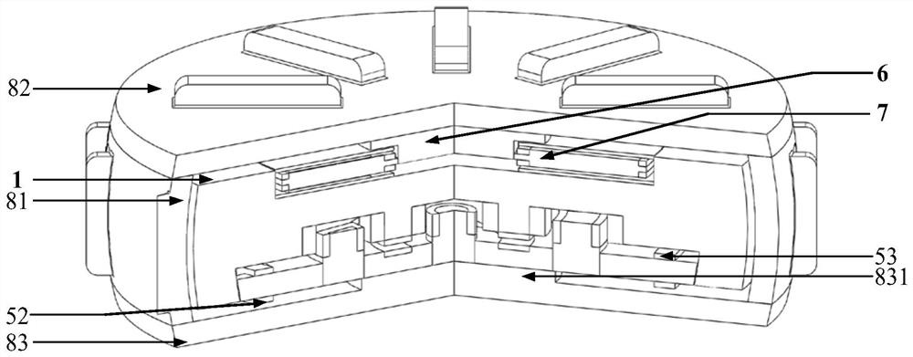
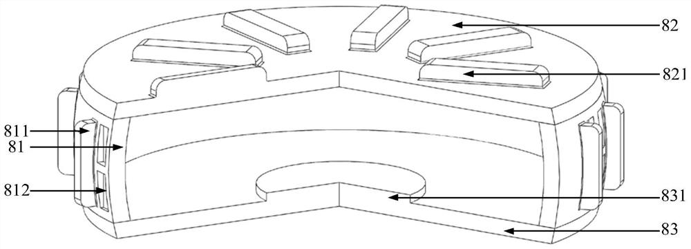
[0049] see figure 1 and combine figure 2 As shown, the outermost part of the present invention is a shell, which is composed of a shell body 81, an upper end cover 82 and a lower end cover 83 sealed and connected, and its material is aluminum foam. The upper end of the shell body 81 is tightly and fixedly connected to the upper end cover 82, and the lower end of the shell body 81 is tightly and fixedly connected to the lower end cover 83. The shell body 81, the upper end cover 82 and the lower end cover 83 form a sealed vacuum chamber to reduce air friction loss. The shell body 81 is a hollow partial spherical shell, with cooling fins 811 and cooling grooves 812 arranged on the outer peripheral surface. It is a square groove, grooved outward along the diameter direction, and every four cooling fins 811 arranged in a square array form a group. Along the circumferential direction, two cooling grooves 812 are symmetrically arranged on both sides of the four cooling fins 811 wi...


PUM


Abstract

The invention discloses an ultra-thin vehicle-mounted magnetic levitation flywheel battery for electric vehicles and a working method thereof. A motor bracket, an axial magnetic flux motor, a flywheel and an inner stator of a five-degree-of-freedom magnetic bearing are coaxially arranged in a casing from top to bottom. , coil and permanent magnet, the flywheel is composed of continuous upper, middle and lower layers. The middle of the upper ring layer of the flywheel on the upper layer is the upper ring groove, and the axial flux motor is placed in the upper ring groove. The groove, the middle annular cavity and the lower annular groove communicate with each other and house the inner stator, coil and permanent magnet of the five-degree-of-freedom magnetic bearing. The five-degree-of-freedom magnetic bearing is axial magnetic bearing, repulsive magnetic bearing, Torsional magnetic bearing and radial spherical magnetic bearing; adopting the mode of multiplexing magnetic bearings of different properties to realize their complementary advantages, which can not only improve the bearing capacity and control accuracy of the magnetic bearing support, significantly improve the stability of the flywheel, but also effectively compensate for the complex The working conditions lead to the problem of large loss of the control coil.

Description

technical field [0001] The invention relates to a flywheel battery, also called a flywheel energy storage device, in particular to a five-degree-of-freedom magnetic levitation flywheel battery for electric vehicles. Background technique [0002] Flywheel battery is a new concept energy storage device. It breaks through the limitations of chemical batteries and realizes physical energy storage through high-speed rotation of flywheel. It has the characteristics of no pollution, high energy conversion efficiency and power density, long cycle life, and insensitivity to temperature. , is a power battery with great development potential in the field of new energy vehicles. However, the current practical application and popularization of vehicle-mounted magnetic levitation flywheel batteries are mainly hindered by occupying a large axial space and facing complex vehicle driving conditions and road conditions (that is, changes in vehicle driving conditions and road conditions, etc.)...

Claims


Application Information

Patent Timeline
Patent Type & Authority Patents(China)
IPC IPC(8): H02K7/02H02K7/09H02N15/00
CPCH02K7/025H02K7/09H02N15/00Y02T10/64Y02E60/16
Inventor 张维煜俞珏鑫单龙朱熀秋李凯张宵啸王振
Owner JIANGSU UNIV
Why Eureka
Try Eureka