Track bridge hoister guiding plate

A track bridge and spreader technology, which is applied in the direction of load hanging components, transportation and packaging, etc. It can solve the problems of falling objects from the bolt guide plate, frequent replacement of spreaders, and affecting work efficiency, so as to reduce time cost and manpower cost, eliminate potential safety hazards, and reduce the effect of inspection and maintenance costs

Inactive Publication Date: 2017-08-11
TIANJIN FIVE CONTINENTS INT CONTAINER TERMINAL
View PDF6 Cites 0 Cited by
  • Summary
  • Abstract
  • Description
  • Claims
  • Application Information

AI Technical Summary

Problems solved by technology

like figure 1 , figure 2 As shown, the currently used spreader guide plate is fixed by 4 bolts. During use, the lower two screws bear most of the force, resulting in easy loosening of the nuts. Only frequent inspection and tightening can ensure the safe working state of the guide plate. ;In addition, there is another situation, when the driver operates the spreader to drop too fast and hit the box or the ground, it is easy to cause the bolts to be cut off. Both the bolts and the guide plate have the danger of falling objects from a high altitude, and there is a great potential safety hazard.
Due to the many failures caused by the guide plate of the spreader, the total time for us to repair the guide plate on site is longer, and the number of times to replace the spreader is too large, which seriously affects the operation efficiency and invests a lot of manpower and material resources. Therefore, the guide plate renovation project can be effective. Reduce the failure rate, improve the safety factor of the equipment, and reduce the investment required for maintenance of the guide plate

Method used


Image

  • Track bridge hoister guiding plate
  • Track bridge hoister guiding plate
  • Track bridge hoister guiding plate

Examples


Embodiment Construction

[0010] The present invention will be described in further detail below in conjunction with the accompanying drawings and specific embodiments. It should be understood that the specific embodiments described here are only used to explain the present invention, not to limit the present invention.

[0011] It should be noted that the "connection" mentioned in this application and the words used to express "connection", such as "connected", "connected", etc., include not only a direct connection between a certain component and another component, but also a certain One part is connected to another part through other parts.

[0012] It should be noted that, in the case of no conflict, the embodiments in the present application and the features in the embodiments can be combined with each other.

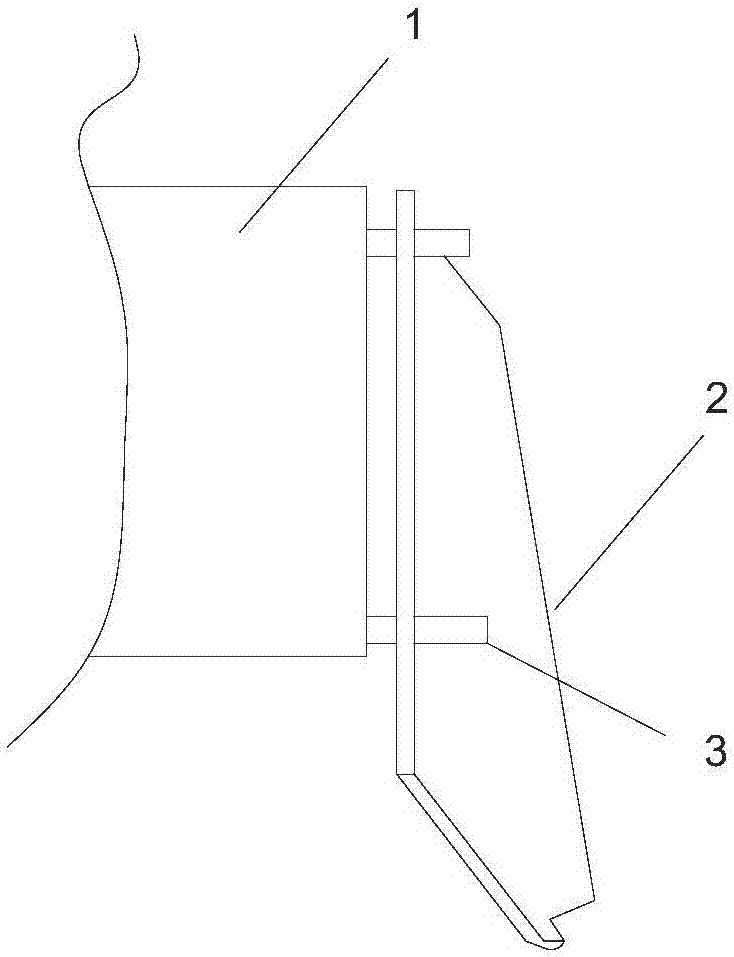
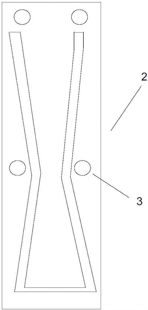
[0013] Such as figure 1 , figure 2 As shown, after an in-depth analysis of the working conditions of the guide plate, it is concluded that the cause of frequent failures is that the bol...


PUM


Abstract

The invention discloses a track bridge hoister guiding plate. The track bridge hoister guiding plate comprises a first structural part and a second structural part. The first structural part is a square frame body. The outer side face of the rear end of the first structural part makes contact with and is welded to the end beam face of a hoister. The lower end of the first structural part is open, and the second structural part is inserted into the first structural part through an opening. The end faces of the two sides of the first structural part and the second structural part are fixedly connected through an upper pin shaft and a lower pin shaft. After transformation of the guiding plate is completed, the force bearing part of a force bearing guiding plate body of the guiding plate can be transferred to the whole guiding plate device through bolts, so that the guiding plate strength is greatly improved, and the guiding plate shock resistance is remarkably improved. Failures caused by cut-off of screws of the guiding plate are eliminated, the fault time of each month can be shortened by 200 minutes at least, replacement times of the hoister can be reduced by six, the guiding plate maintaining cost is about 4550 yuan, more importantly, the potential safety hazards caused by objects falling from high altitudes are greatly eliminated, and the equipment safety coefficient is increased.

Description

technical field [0001] The invention relates to the technical field of container cranes, in particular to a rail bridge spreader guide plate. Background technique [0002] The spreader is a key part of the container crane. During the operation, the spreader constantly collides with and impacts the container. Although the spreader guide plate is working continuously, most operators still hope to be faster, which is even more strengthened. The impact of the box on the guide plate is eliminated. Such as figure 1 , figure 2 As shown, the currently used spreader guide plate is fixed by 4 bolts. During use, the lower two screws bear most of the force, resulting in easy loosening of the nuts. Only frequent inspection and tightening can ensure the safe working state of the guide plate. ; Due to the many failures caused by the guide plate of the spreader, the total time for us to repair the guide plate on site is longer, and the number of times to replace the spreader is too lar...

Claims


Application Information

Patent Timeline
Patent Type & Authority Applications(China)
IPC IPC(8): B66C1/10
CPCB66C1/101
Inventor 马会军马国学信毅王洪亮魏俊林陈培王福忠季成唐友范唯林宏彬吕靖轩王毅刚陈彦周小峰张彪蔡少咏孙占旺刘鑫
Owner TIANJIN FIVE CONTINENTS INT CONTAINER TERMINAL
Why Eureka
Try Eureka