Radiation sensitivity test method and device under reverberation chamber condition

A technology of radiation sensitivity and testing method, applied in the field of radiation sensitivity testing method and device, capable of solving problems such as large difference in uniform field

Active Publication Date: 2017-08-11
PEOPLES LIBERATION ARMY ORDNANCE ENG COLLEGE
View PDF5 Cites 7 Cited by
  • Summary
  • Abstract
  • Description
  • Claims
  • Application Information

AI Technical Summary

Problems solved by technology

[0003] In view of this, the embodiment of the present invention provides a radiation sensitivity test method and device to solve th...

Method used


Image

  • Radiation sensitivity test method and device under reverberation chamber condition
  • Radiation sensitivity test method and device under reverberation chamber condition
  • Radiation sensitivity test method and device under reverberation chamber condition

Examples


Embodiment 1

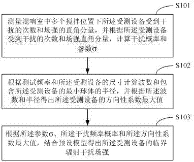
[0041] figure 1 The implementation flow of the radiation sensitivity testing method provided by Embodiment 1 of the present invention is shown, and the details are as follows:

[0042] Step S101, measure the number of times the device under test is disturbed and the right-angle component of the field strength at multiple stirring positions in the reverberation chamber, and calculate the interference probability and Parameter σ.

[0043] The electric field in the reverberation chamber changes randomly according to certain statistical laws. From the perspective of electric field measurement, it is difficult to correspond the magnitude of the electric field in the reverberation chamber with that in the uniform field. However, if it is assumed that no matter what kind of field environment the device under test is in, as long as the received power of the sensitive components of the device under test is greater than its critical interference power, the device under test will be int...

Embodiment 2

[0155] Corresponding to the radiation sensitivity test method described in the first embodiment above, Figure 24 A structural block diagram of the radiation sensitivity testing device provided by Embodiment 2 of the present invention is shown. For ease of description, only the parts related to this embodiment are shown.

[0156] refer to Figure 24 , the device includes a measurement calculation module 101 , a processing module 102 and a model calculation module 103 . The measurement and calculation module 101 is used to measure the number of times the device under test is disturbed and the right-angle component of the field strength at multiple stirring positions in the reverberation chamber, and according to the number of times the device under test is disturbed and the right-angle component of the field strength, Calculate the interference probability and the parameter σ. The processing module 102 is used to calculate the wave number and the radius of the smallest spher...


PUM


Abstract

The invention relates to the electromagnetic technology field and provides a radiation sensitivity test method and device under the reverberation chamber condition. The method comprises steps that interfered frequency of tested equipment and right angle components of field intensity at multiple stirring positions in a reverberation chamber are measured, according to the interfered frequency of the tested equipment and the right angle components, an interference probability and a parameter sigma are calculated; according to test frequency and dimensions of the tested equipment, a wave number and a radius of a smallest ball capable of containing the tested equipment are calculated, and a maximum directivity coefficient of the tested equipment is acquired according to the wave number and the radius; according to the parameter sigma, the interference frequency and the maximum directivity coefficient, critical radiation interference field intensity of the tested equipment can be acquired in combination with a preset model. The method is advantaged in that a problem of poor correlation between the radiation sensitivity test result of the tested equipment in the reverberation chamber and a uniform field is solved, the method is especially suitable for complex large-size equipment, and a new concept is provided for the radiation sensitivity test on the equipment under the reverberation chamber condition.

Description

technical field [0001] The invention belongs to the field of electromagnetic technology, and in particular relates to a radiation sensitivity testing method and device under reverberation chamber conditions. Background technique [0002] With the rapid development of microelectronics technology, electronic equipment tends to be miniaturized and integrated gradually, and the electromagnetic environment inside the equipment and its working site is becoming more and more complex. Radiation sensitivity testing is an important means to evaluate the electromagnetic protection performance of equipment before the equipment is finalized. As an emerging test site, the reverberation chamber is generally used for the passability test of the radiation sensitivity of the equipment, and it is still to be studied for the critical radiation interference field strength test. Due to the statistically uniform electromagnetic environment inside the reverberation chamber, the radiation sensitivi...

Claims


Application Information

Patent Timeline
IPC IPC(8): G01R31/00
Inventor 魏光辉胡德洲潘晓东万浩江卢新福
Owner PEOPLES LIBERATION ARMY ORDNANCE ENG COLLEGE
Why Eureka
Try Eureka