Power supply structure

A technology of electrical components and plugs, applied in the direction of circuits, electrical components, conductive connections, etc., can solve the problems of poor installation performance and difficulty of motor 104, and achieve the effects of low manufacturing cost, restraining inclination, and improving installation performance

Active Publication Date: 2019-12-03
U SHIN LTD
View PDF5 Cites 0 Cited by
  • Summary
  • Abstract
  • Description
  • Claims
  • Application Information

AI Technical Summary

Problems solved by technology

[0013] However, as proposed in Patent Document 1 Figure 12 as well as Figure 13 In the power supply structure shown, the plug protrusions 105B, 106B of the bus bars 105, 106 may be arranged obliquely to the housing 102. In this case, by inserting the plug protrusions 105B, 106B of the bus bars 105, 106 into the It is not easy to install the motor 104 in the socket recesses 104a, 104b on the motor 104, and the installation performance of the motor 104 will deteriorate.

Method used


Image

  • Power supply structure
  • Power supply structure
  • Power supply structure

Examples


Embodiment Construction

[0079] Embodiments of the present invention will be described below based on the drawings.

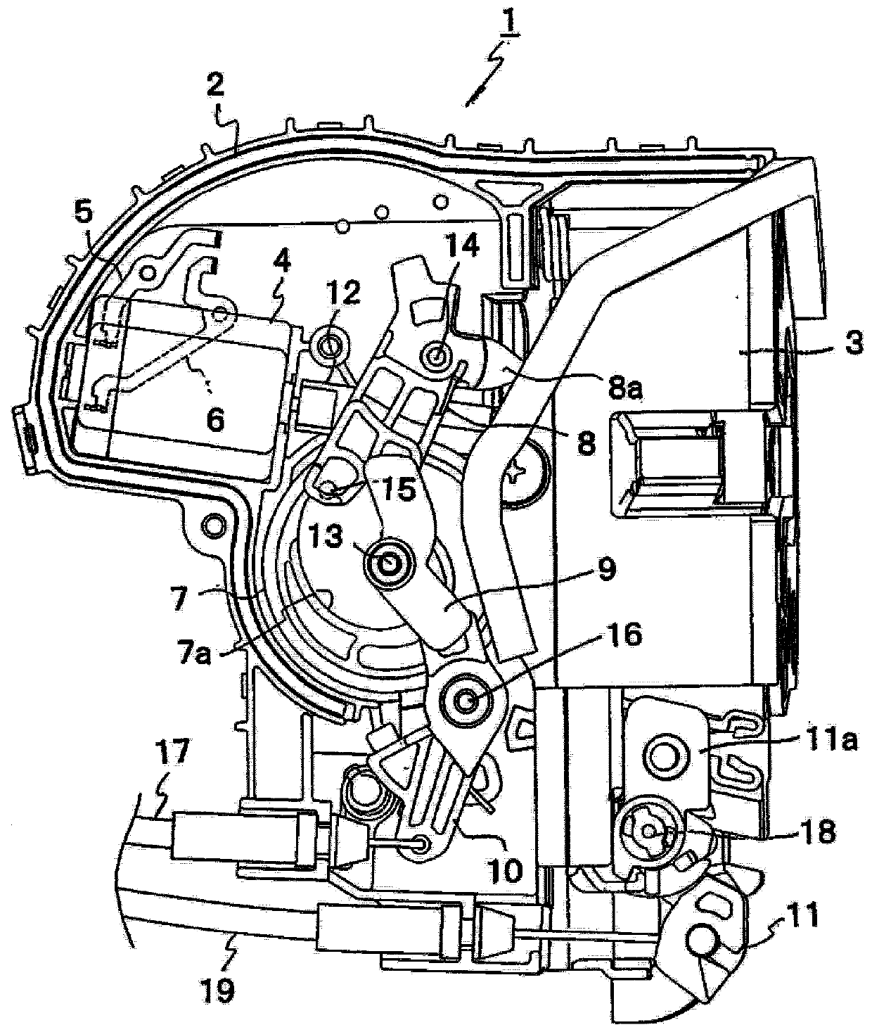
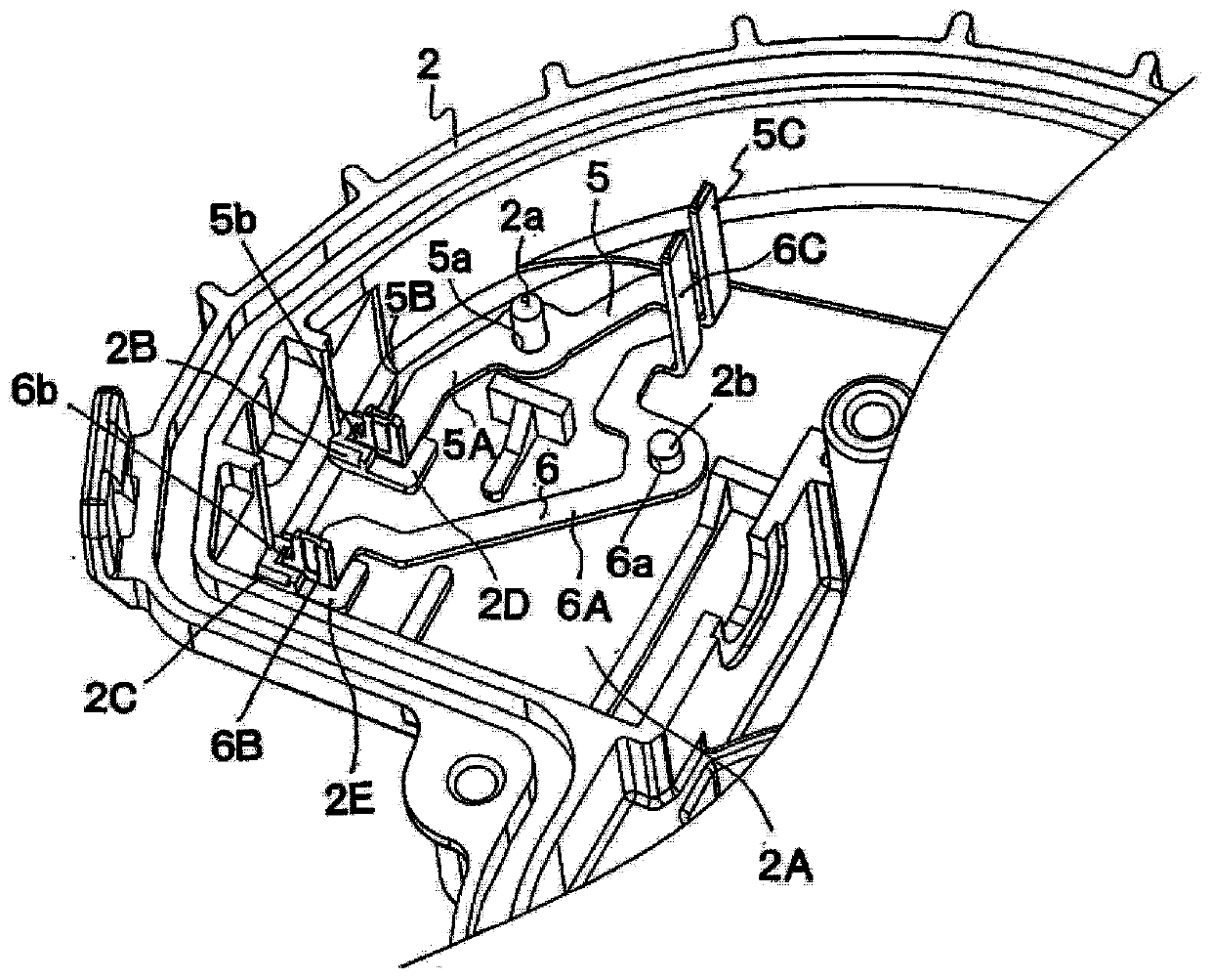
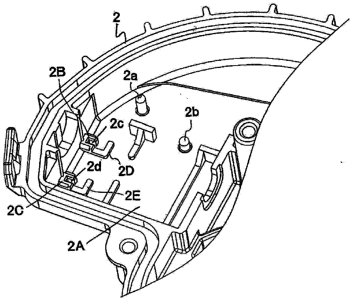
[0080] figure 1 It is a plan view showing the internal structure of a door lock device provided with a power supply structure for supplying power to a motor according to the present invention, figure 2 It is a partial perspective view showing the state before the motor is installed in the door lock device having the power supply structure, image 3 It is a partial perspective view of the lower case showing the state before the bus bar and the motor of the door lock device having the power supply structure are attached, Figure 4 is a plan view of the plug convex portion of the bus bar, Figure 5 is the front view of the plug protrusion of the bus bar, Image 6 is a partial plan view showing a state in which the plug protrusion of the bus bar is engaged with the support portion of the lower case, Figure 7 It is a partial sectional view showing the mounted state of the motor.

[...


PUM


Abstract

To provide a structure for power supply to an electric motor capable of improving assemblability of the electric motor by preventing plug projections of bus bars from being tilted. In the structure, an electric motor 4 and bus bars 5 and 6 are disposed in a base member 2 and power is supplied from a power source through the bus bars 5 and 6 to the electric motor 4. The structure for power supply to the electric motor 4 is configured by forming plug projections 5B and 6B while bending them at right angles in one end of main body parts 5A and 6A of the bus bars 5 and 6 extending along an inner surface of the lower case 2, and electrically connecting the bus bars 5 and 6 and the electric motor 4 by inserting the plug projections 5B and 6B into receptacle recesses 4a that are formed in the electric motor 4. Lock pieces 5b and 6b are provided protrusively in the plug projections 5B and 6B of the bus bars 5 and 6, and support parts 2B and 2C which are positioned at both sides of the lock pieces 5b and 6b in a thickness direction and support the lock pieces 5b and 6b, are provided in the lower case 2.

Description

technical field [0001] The present invention relates to a power supply structure for supplying power from a power source to a motor or the like via a busbar. Background technique [0002] For example, a door lock device for locking / unlocking a car door with respect to the vehicle body needs to have high waterproof and anti-theft functions. Therefore, in recent years, multiple control A structure in which a lever, a motor, and the like are arranged in a sealed resin housing (base member). [0003] However, although a motor is used as a drive source in the door lock device, power is supplied from a power source to the motor via a bus bar (conductive terminal) as a power supply structure for supplying power to the motor. In this case, the bus bar is integrally formed with the housing by insert molding. [0004] However, as described above, in order to integrally form the bus bar and the housing by insert molding, not only the process of attaching the bus bar to the housing in...

Claims


Application Information

Patent Timeline
Patent Type & Authority Patents(China)
IPC IPC(8): H01R11/01H01R11/11
CPCH01R11/01H01R11/11H01R9/226H01R13/42
Inventor 芥川胜利赤木伸哉山崎浩平
Owner U SHIN LTD
Why Eureka
Try Eureka