Bridge hoisting equipment

A technology for hoisting equipment and bridges, which is applied in the direction of bridge construction, bridge erection/assembly bridges, etc. It can solve problems such as uneven distribution of suspension ropes, troublesome replacement of rope shafts, and bulky cranes, so as to prevent uneven rope collection and improve The effect of improving the rope receiving speed and improving the running stability

Inactive Publication Date: 2017-08-15
何胜利
View PDF0 Cites 1 Cited by
  • Summary
  • Abstract
  • Description
  • Claims
  • Application Information

AI Technical Summary

Problems solved by technology

Traditional man-made cable hoisting is time-consuming, labor-intensive, poor in stability, and slow in speed; large cranes are bulky and unsuitable in many occasions with insufficient space; some automatic rope-retracting equipment uses a turntable to r

Method used


Image

  • Bridge hoisting equipment
  • Bridge hoisting equipment
  • Bridge hoisting equipment

Examples


Example Embodiment

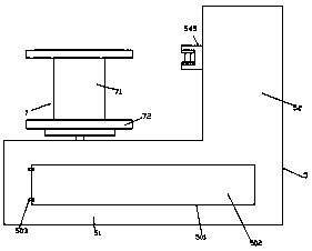
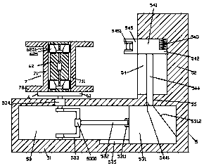
[0020] Such as Figure 1-Figure 5 As shown, a bridge hoisting equipment of the present invention includes a rope take-up base 5 composed of a first base 51 and a second base 52. The first base 51 is provided with an inner cavity 53 extending left and right. The right side of the cavity 53 is provided with a first sliding connection groove 535, and a sliding connection block 531 is provided in the first sliding connection groove 535, which is connected by sliding connection, and the left side of the sliding connection block 531 in the inner cavity 53 A pin sleeve 5311 is provided on the pin sleeve 5311, a push rod 532 extending to the left is transferred into the pin sleeve 5311, a pin sleeve 5331 is provided at the left end of the push rod 532, and the pin sleeve 5331 A curved pin shaft 533 is provided inside, the front side of the curved pin shaft 533 is adapted to the front inner wall of the inner cavity 53, and the rear side of the curved pin shaft 533 is matedly connected w...


PUM


Abstract

The invention discloses bridge hoisting equipment. The bridge hoisting equipment comprises a rope take-up base body composed of a first base body and a second base body. An inner cavity arranged in a left-and-right extending manner is formed in the first base body. A first slip groove is formed in the right side of the inner cavity. A slip block connected in a slip fit manner is arranged in the first slip groove. A pin shaft sleeve is arranged on the left side face of the slip block in the inner cavity. A pushing rod arranged in a leftward extending manner is rotationally connected in the pin shaft sleeve. A pin shaft sleeve is arranged at the tail of the left side of the pushing rod and is internally provided with a curved pin shaft. The front side of the curved pin shaft is rotationally connected with the inner wall of the front side of the inner cavity. The rear side of the curved pin shaft is connected with a rope take-up electric rotating machine in a matched manner. The rope take-up electric rotating machine is arranged in the inner wall of the rear side of the inner cavity and is fixedly connected. A second slip groove arranged in a front-and-back extending manner is formed in the left side face of the second base body. A second slip block is arranged in the second slip groove. The bridge hoisting equipment is simple in structure, fast mounting and demounting can be achieved, the replacement speed of a rope winding drum can be increased, and uniform rope take-up work can be achieved.

Description

technical field [0001] The invention relates to the field of bridges, in particular to bridge hoisting equipment. Background technique [0002] In the process of bridge construction, it is often necessary to hoist materials such as silt concrete, steel pipe fittings, etc. from a low place to the bridge through hoisting equipment. Traditional man-made cable hoisting is time-consuming, labor-intensive, poor in stability, and slow in speed; large-scale cranes are bulky and unsuitable in many occasions where space is insufficient; some automatic rope-retracting equipment uses a turntable to retract the rope when retracting the rope, but these devices often There will be uneven distribution of the suspension rope on the rope reel, which greatly affects the stability of the rope collection, and it is very troublesome to replace the rope shaft. Contents of the invention [0003] The technical problem to be solved by the present invention is to provide a bridge hoisting device, w...

Claims


Application Information

Patent Timeline
IPC IPC(8): B66D1/28B66D1/30E01D21/00
CPCB66D1/28B66D1/30B66D2700/0141E01D21/00
Inventor 何胜利
Owner 何胜利
Why Eureka
Try Eureka