Travelling control system and method of electronic fuel injection engine wheel type hydraulic excavator

A hydraulic excavator and driving control technology, applied in the direction of earth mover/shovel, construction, etc., can solve the problems of low engine power utilization rate, fuel waste, engine stall and other problems, and achieve strong ability to adapt to harsh road conditions, Good driving comfort and smooth driving effect

Active Publication Date: 2017-08-15
GUIZHOU JONYANG KINETICS
View PDF7 Cites 7 Cited by
  • Summary
  • Abstract
  • Description
  • Claims
  • Application Information

AI Technical Summary

Problems solved by technology

Therefore, the engine power utilization rate is very low when driving, the fuel consumption is high, and the driving stability is also poor. If the user forgets to press the parking brake and drives the machine, it will cause the engine to stall.
[0003]Imported wheel excavators adopt the relationship between the stroke of the accelerator pedal and the engine speed, or check the travel pump pressure to participate in the control of the engine speed and the limited power of the pump. The engine power is matched, but it does not distinguish between various driving conditions and the equivalent fuel consumption characteristics for analysis and utilization, such as bumpy roads, muddy roads, climbing, etc.
In addition, if the foot shakes, it will cause the accelerator and the hydraulic system to shake, so there is still a lot of fuel waste, and the driving stability is not high, so the existing driving control method for wheeled hydraulic excavators with EFI engines is still not perfect.

Method used


Image

  • Travelling control system and method of electronic fuel injection engine wheel type hydraulic excavator
  • Travelling control system and method of electronic fuel injection engine wheel type hydraulic excavator
  • Travelling control system and method of electronic fuel injection engine wheel type hydraulic excavator

Examples


Embodiment Construction

[0017] The present invention will be further described in detail below in conjunction with the accompanying drawings and embodiments, but not as a limitation to the present invention.

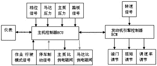
[0018] Embodiment of the present invention: a driving control system for a wheeled hydraulic excavator with an EFI engine, including a host controller ECU1, the host controller ECU1 communicates with the engine assembly 2, the parking brake button 3, the instrument 4, and the steering wheel through wires. The engine 5, the accelerator pedal 6 are connected with the working driving mode switch 7, the engine assembly 4 is connected with the main pump 8 through the coupling, and the main pump 8 is connected with the motor 9 through the hydraulic oil circuit, on the main pump 8 A driving pump pressure transmitter 11 and a main pump proportional solenoid valve 12 are provided, and a motor proportional solenoid valve 10 is provided on the motor 9. The main pump proportional solenoid valve 12 and the m...


PUM


Abstract

The invention discloses a travelling control system and method of an electronic fuel injection engine wheel type hydraulic excavator. In the travelling process of the electronic fuel injection engine wheel type hydraulic excavator, a host controller ECU collects the travel signal of an accelerator pedal, the travelling gear signal of a steering gear, the pressure signal of a motor, the pressure signal of a main pump and the signal of a parking brake button; a rotating speed signal sent by an ECM is collected through a CAN bus; the current of a main pump proportional electromagnetic valve and a motor proportional electromagnetic valve is controlled; and an engine accelerator and the torque of the engine are controlled through the CAN bus. The travelling control system and method are better in power matching and characteristic matching of the main pump and the engine, matching of different working condition loads and the power of the main pump, matching of different working conditions and the torque of the engine and matching of the different working conditions and the torque of a motor, so that the travelling control system and method have the advantages that the electronic fuel injection engine wheel type hydraulic excavator saves more energy and is higher in capability of adapting to severe road conditions, more stable in travelling and better in driving comfort, and the situation that a user forgets that the parking brake button is already pressed and drives the excavator when the parking brake button is already pressed, and consequentially the engine flames out due to suppression is avoided.

Description

technical field [0001] The patent of the invention relates to a driving control system and a control method of a wheeled hydraulic excavator with an electric injection engine, and belongs to the technical field of wheeled hydraulic excavator control systems. Background technique [0002] At present, domestic wheeled excavators generally do not have special control in terms of driving control. What has been done better is to borrow the control strategy of crawler excavators, and adopt power matching and limit power control at fixed speeds for the power matching of pumps and engines. But when driving, it is impossible for the driver to change the accelerator gear in time, so the accelerator needs to be adjusted to a certain gear before driving, and work at a certain engine speed. The specificity of driving is different from excavation, and the torque, speed, stability requirements and fuel consumption of each working condition and high-speed and low-speed gears during driving ...

Claims


Application Information

Patent Timeline
Patent Type & Authority Applications(China)
IPC IPC(8): E02F9/22
CPCE02F9/2253
Inventor 王锐军高山铁谭林全杨玉华陈代洪李林王安源
Owner GUIZHOU JONYANG KINETICS
Why Eureka
Try Eureka