V-shaped double-cylinder type general engine fuel supply device

A technology for a fuel supply device and a general-purpose engine, which is applied to fuel injection devices, engine components, engine control, etc., can solve problems such as narrow engine covers, insufficient number of components, and differences in air-fuel ratios, achieving easy design and simple sharing. , the effect of eliminating exhaust gas restriction

Inactive Publication Date: 2017-08-15
NIKKI CO LTD
View PDF1 Cites 4 Cited by
  • Summary
  • Abstract
  • Description
  • Claims
  • Application Information

AI Technical Summary

Problems solved by technology

[0006] The fuel supply device for a general-purpose engine disclosed in the above-mentioned gazette realizes cost reduction by adopting a so-called SPI (Single Point Injection: Single Point Injection) method in which fuel is injected into each cylinder of a two-cylinder engine using one fuel injection valve. but if Figure 14 As shown, a fuel injection valve 11a is provided on the upstream side of the throttle body 2a, 2a, and the throttle body 2a, 2a is a throttle valve connected to the intake manifold 3a having two branch pipes M1, M2. 5a is configured in two channel parts T 1 , T 2 , the two branches M 1 , M 2 Respectively with two cylinders C of twin-cylinder engine 4a 1 、C 2 As for the connection, the fuel injection valve 11a is arranged on the throttle body 2a, and the cost reduction due to the reduction in the number of parts can be confirmed, but since it is necessary to have two branch pipes M connected to the engine cylinder 1 , M 2 The intake manifold 3a and the throttle valve main body 2a equipped with two throttle valves 5a, 5a, therefore, the number of parts is not sufficiently reduced. In addition, it is necessary for the injection fuel from the fuel injection valve 11a to flow into the passage portion T 1 , T 2 part of the pathway T 1 , T 2 , as a whole is a complex structure that is not easy to fabricate
[0007] In particular, since the intake manifold 3a including the throttle valves 5a, 5a, and the branch pipes M1, M2 is disposed downstream of the branch of the fuel injection valve 11a, even if it is difficult to divide the fuel injection valve into two equal parts with a correct structure, the Divide the injected fuel from one fuel injection valve 11a to the fuel guide F 1 , F 2 , there is also the problem that the air intake amount changes according to the load of the internal combustion engine, so that before reaching the cylinder, the air-fuel ratio in each cylinder will be different. In addition, the fuel supply device disclosed in the above-mentioned publication can be arranged between each cylinder There is a parallel twin-cylinder engine with a space for the fuel supply device to be installed, but for a V-shaped twin-cylinder general-purpose engine that has been further downsized, since the mutual engine covers are formed narrow, the installation itself is very difficult. difficulty
[0008] In addition, Japanese Patent Application Laid-Open No. 63-87271 (Patent Document 2) discloses a fuel supply device in which the throttle valve is arranged upstream of the fuel injection valve, but it is disclosed that the sprayed fuel injected from the fuel injection valve Introduction of a fuel supply device that guides the left and right intake branch pipes from the vertical plate to supply to each cylinder, and cannot be applied to an air-cooled general-purpose engine that does not have a vertical plate
[0009] In addition, since there are vertical output shaft types such as passenger lawn mowers and horizontal output shaft types such as generators in the V-twin general-purpose engine, and the intake manifold of the vertical output shaft type In the intake manifold of the pipe and horizontal output shaft type, the installation angle of the throttle body is staggered by 90 degrees. The injection direction of the fuel does not match the intake manifold of each type, so it is necessary to prepare the intake manifold of each output shaft type separately, and there is a problem in that the production efficiency is improved by the common use of parts. question

Method used


Image

  • V-shaped double-cylinder type general engine fuel supply device
  • V-shaped double-cylinder type general engine fuel supply device
  • V-shaped double-cylinder type general engine fuel supply device

Examples


Embodiment Construction

[0076] Hereinafter, preferred embodiments of the present invention will be described in detail with reference to the drawings.

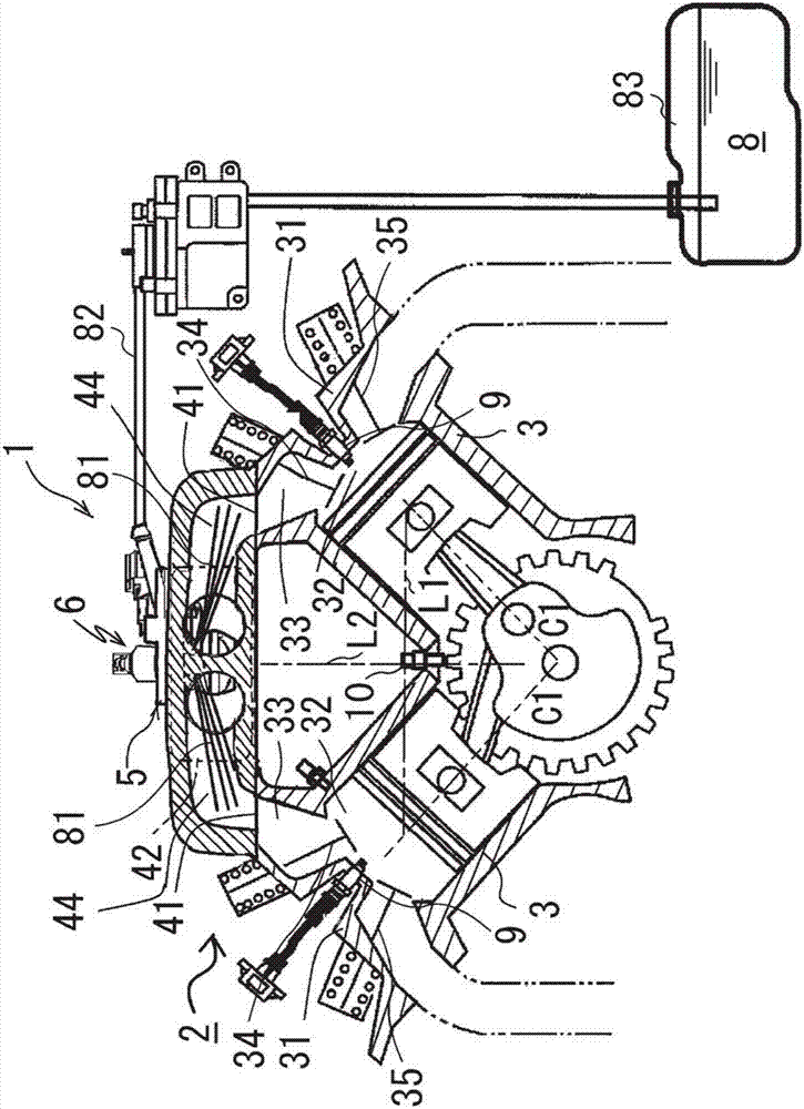
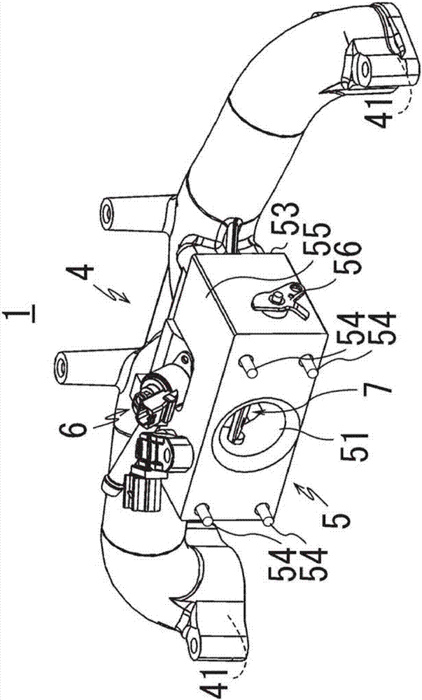
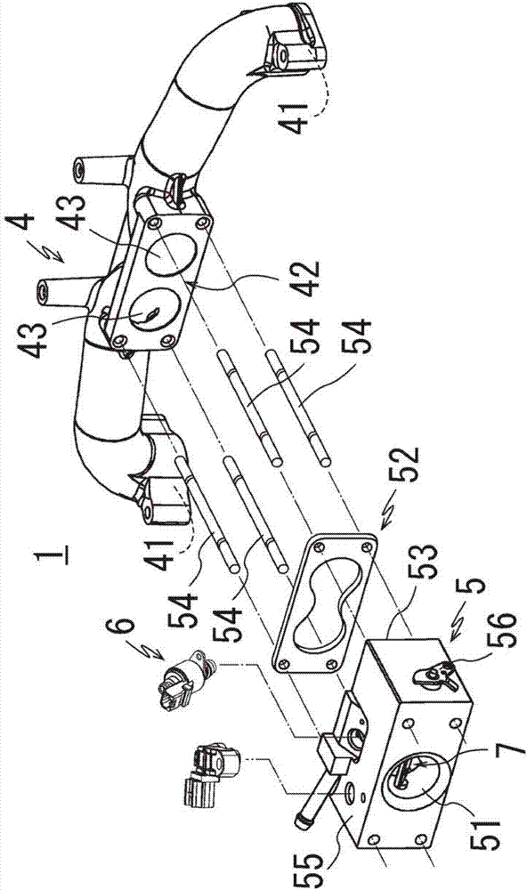
[0077] Figure 1 to Figure 6 It is a diagram showing a preferred embodiment when the present invention is implemented in a vertical output shaft type V-type general-purpose engine used in, for example, a passenger lawn mower, and the fuel supply device 1 is provided on a V-type two-cylinder general-purpose engine 2 For example, in an air-cooled general-purpose engine having a cylinder hole angle (Japanese: boa angle) of 90 degrees with cylinders 3 and 3, the fuel supply device 1 is mainly formed by an intake manifold 4 and a throttle body 5, wherein, The openings 41, 41 at both ends of the intake manifold 4 are connected to the intake ports 32, 32 of the cylinder heads 31, 31 of the cylinders 3, 3, and the throttle body 5 is connected to the intake ports formed on the intake manifold. 4 at the middle position of the planar connecting portion 42 conn...


PUM


Abstract

The invention discloses a V-shaped double-cylinder type general engine fuel supply device. By using less and cheap parts, fuel in various cylinders are uniformly distributed to eliminate gas exhaust limitation, and the V-shaped double-cylinder type general engine fuel supply device can be disposed on a narrow V-shaped double-cylinder general engine disposed between engine covers, and a difference between the air-fuel ratios of the various cylinders cannot be caused, and therefore the optimal cylinder distribution is realized. The V-shaped double-cylinder type general engine fuel supply device comprises an air supply manifold, two ends of which are connected with the gas inlets of the engine cover of the cylinders of the V-shaped double-cylinder type general engine; a throttle main body, which is connected with the connecting part of the gas inlet manifold; a fuel injection valve, which is provided with a nozzle disposed on the throttle main body and used to inject the fuel to the inner side of the gas inlet ports of the various cylinders or the inner wall surfaces of the gas inlet ports by the connecting part of the gas inlet manifold; and a gas throttle valve, which is disposed on the upstream of the fuel injection valve of the throttle main body.

Description

technical field [0001] The invention relates to a fuel supply device for a V-shaped twin-cylinder general-purpose engine used in lawnmowers, generators, and power machines for water recreation. Background technique [0002] In the past, general-purpose engines used as lawnmowers, engines, power machines for water sports, etc. have been known. In particular, general-purpose engines are required to be small and inexpensive in view of their purpose of use, and most of these general-purpose engines use carburetors. As a fuel supply unit. [0003] However, it is extremely difficult to implement the function of carburetor that complies with the exhaust measures of recent engines due to structural limitations. That is, the distribution of the cylinders is likely to be different, and for this reason, a structure in which the carburetor is independent for each cylinder is adopted. [0004] In addition, for example, in such a multi-cylinder engine used in expensive automobiles, by r...

Claims


Application Information

Patent Timeline
Patent Type & Authority Applications(China)
IPC IPC(8): F02M35/10F02M35/116F02M69/04
CPCF02M35/10216F02M35/116F02M69/042Y02T10/12
Inventor 木村和树足立良太若林晃之末松幸伦谷川翔太
Owner NIKKI CO LTD
Why Eureka
Try Eureka