
Intelligent induction lamp controlled electronically

An electronic control and induction lamp technology, applied in energy-saving control technology, lamp circuit layout, electric light source, etc., can solve the problems of energy shortage, energy shortage, corridor lights can only be switched on or off by time or manually

Inactive Publication Date: 2017-08-15
陈德成
View PDF5 Cites 1 Cited by
  • Summary
  • Abstract
  • Description
  • Claims
  • Application Information

AI Technical Summary

Problems solved by technology

[0002] At present, with the rapid development of the economy, the problem of energy shortage has become increasingly prominent, becoming a "bottleneck" of a country's economic development, especially as an indispensable power source for industrial production and people's lives, especially now that low-carbon life is increasingly advocated , saving energy has become a global consensus, and colleges and universities that cultivate social elites should play an exemplary role. With the development of social economy and science and technology, people's living standards are also constantly improving, which leads to the intensification of electricity load. And because of the worldwide energy crisis, the lack of energy has become a serious problem facing the world, and this problem is particularly serious for our country. Ordinary corridor lights can only be switched on or off manually, which wastes power resources. People An intelligent sensor light is needed to facilitate life and save resources

Method used


Image

  • Intelligent induction lamp controlled electronically
  • Intelligent induction lamp controlled electronically
  • Intelligent induction lamp controlled electronically

Examples


Embodiment Construction

[0018] The specific embodiments of the present invention will be further described below in conjunction with the accompanying drawings. It should be noted here that the descriptions of these embodiments are used to help understand the present invention, but are not intended to limit the present invention. In addition, the technical features involved in the various embodiments of the present invention described below may be combined with each other as long as they do not constitute a conflict with each other.

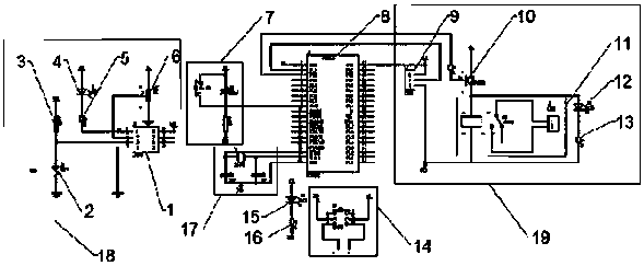
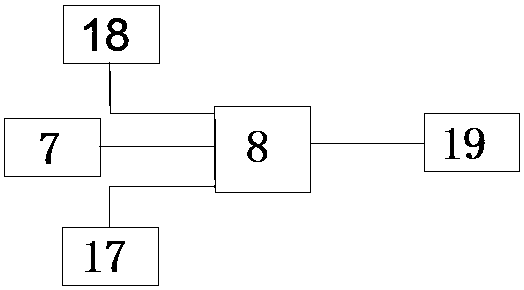
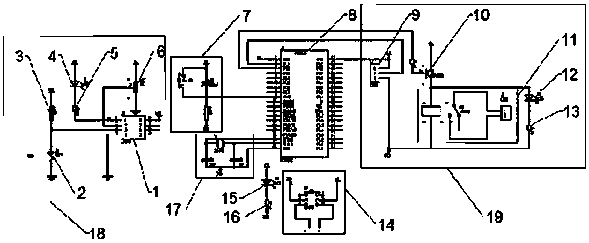
[0019] see figure 1 and figure 2 , the present invention provides a technical solution: an electronically controlled intelligent induction lamp, including a voltage comparator 1, the model of the voltage comparator 1 is LM393, and the voltage comparator 1 includes a light intensity indicator light 4, a photoresistor 2, Reference voltage 6, central controller 8, a light intensity indicator 4 is connected to the left side of the voltage comparator 1, and a current-limit...


PUM


Abstract

The invention discloses an intelligent induction lamp controlled electronically. The intelligent induction lamp comprises a voltage comparator, wherein a light ray intensity indication lamp is connected with a left side of the voltage comparator, a photoresistor is arranged at a left side of the light ray intensity indication lamp, a central controller is connected with a lower part of the light ray intensity indication lamp, a reset circuit is connected with a middle part of a left side of the central controller, a crystal oscillation circuit is connected with a lower part of the left side of the central controller, a pyroelectric infrared sensor is connected with a right side of the central controller, a relay is connected with a right side of the pyroelectric infrared sensor, and the intelligent induction lamp is connected with a right side of the relay. In the intelligent induction lamp controlled electronically, the light ray intensity indication lamp is arranged, so that light ray intensity can be judged by people; a current-limiting resistor II is arranged, so that the light ray intensity indication lamp is prevented from being burnt; by arranging the reset circuit, the central controller can normally work; and by arranging the intelligent induction lamp, the people can judge whether a human body is detected by the device or not.

Description

technical field [0001] The invention relates to the technical field of intelligent induction lamps, in particular to an electronically controlled intelligent induction lamp. Background technique [0002] At present, with the rapid development of the economy, the problem of energy shortage has become increasingly prominent, becoming a "bottleneck" of a country's economic development, especially as an indispensable power source for industrial production and people's lives, especially now that low-carbon life is increasingly advocated , saving energy has become a global consensus, and colleges and universities that cultivate social elites should play an exemplary role. With the development of social economy and science and technology, people's living standards are also constantly improving, which leads to the intensification of electricity load. And because of the worldwide energy crisis, the lack of energy has become a serious problem facing the world, and this problem is part...

Claims


Application Information

Patent Timeline
IPC IPC(8): H05B37/02
CPCH05B47/105H05B47/11Y02B20/40
Inventor 陈德成
Owner 陈德成
Learn More