Shoe gluing device

A technology for shoes and mobile devices, which is applied in the field of gluing devices, and can solve problems such as inaccurate gluing of shoes, waste of glue, and difficulty in controlling the amount of gluing

Inactive Publication Date: 2017-08-18
林永贵
View PDF7 Cites 7 Cited by
  • Summary
  • Abstract
  • Description
  • Claims
  • Application Information

AI Technical Summary

Problems solved by technology

[0006] In order to overcome the shortcomings of manual shoe gluing, such as difficulty in controlling the amount of gluing, wasting unnecessary glue, and inaccurate shoe gluing, the technical problem to be solved by the invention is to provide a shoe gluing device

Method used


Image

  • Shoe gluing device
  • Shoe gluing device
  • Shoe gluing device

Examples


Embodiment 1

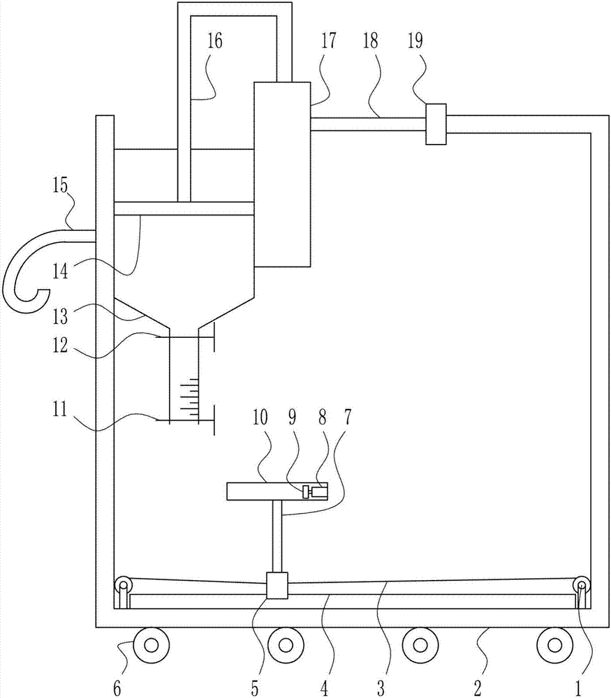
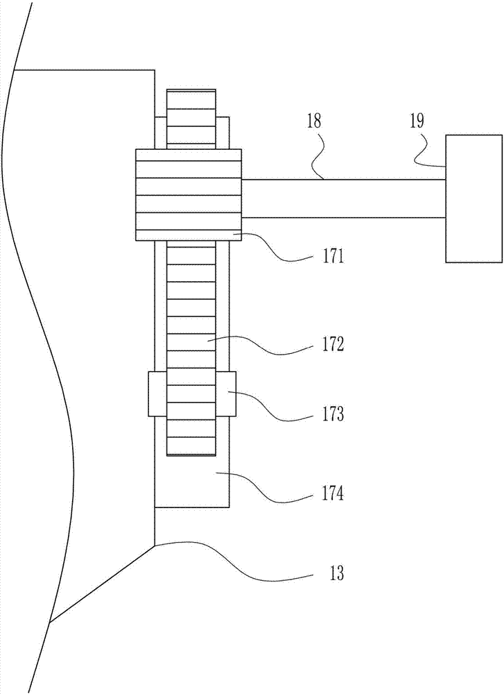
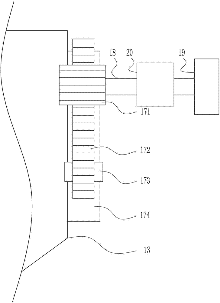
[0029] A shoe gluing device, such as Figure 1-6As shown, it includes an electric reel 1, a bracket 2, a pull cord 3, a first slide rail 4, a first slider 5, a roller 6, a pole 7, an electric push rod 8, an arc stopper 9, a shoe-shaped Tank body 10, first valve 11, second valve 12, transparent plastic box 13, piston 14, handle 15, connecting rod 16, moving device 17, rotating shaft 18 and motor 19, the bottom outside the bracket 2 is uniformly provided with rollers 6 , a handle 15 is provided on the left side wall outside the bracket 2, a first slide rail 4 is provided at the inner bottom of the bracket 2, and an electric reel 1 is provided at the inner bottom of the bracket 2 on the left and right sides of the first slide rail 4, and the electric winding Pull cords 3 are wound around the reels 1, and the ends of the draw cords 3 are connected to the first slider 5, and the top of the first slider 5 is connected to a strut 7, and the upper end of the strut 7 is provided with a...

Embodiment 2

[0031] A shoe gluing device, such as Figure 1-6 As shown, it includes an electric reel 1, a bracket 2, a pull cord 3, a first slide rail 4, a first slider 5, a roller 6, a pole 7, an electric push rod 8, an arc stopper 9, a shoe-shaped Tank body 10, first valve 11, second valve 12, transparent plastic box 13, piston 14, handle 15, connecting rod 16, moving device 17, rotating shaft 18 and motor 19, the bottom outside the bracket 2 is uniformly provided with rollers 6 , a handle 15 is provided on the left side wall outside the bracket 2, a first slide rail 4 is provided at the inner bottom of the bracket 2, and an electric reel 1 is provided at the inner bottom of the bracket 2 on the left and right sides of the first slide rail 4, and the electric winding Pull cords 3 are wound around the reels 1, and the ends of the draw cords 3 are connected to the first slider 5, and the top of the first slider 5 is connected to a strut 7, and the upper end of the strut 7 is provided with ...

Embodiment 3

[0034] A shoe gluing device, such as Figure 1-6 As shown, it includes an electric reel 1, a bracket 2, a pull cord 3, a first slide rail 4, a first slider 5, a roller 6, a pole 7, an electric push rod 8, an arc stopper 9, a shoe-shaped Tank body 10, first valve 11, second valve 12, transparent plastic box 13, piston 14, handle 15, connecting rod 16, moving device 17, rotating shaft 18 and motor 19, the bottom outside the bracket 2 is uniformly provided with rollers 6 , a handle 15 is provided on the left side wall outside the bracket 2, a first slide rail 4 is provided at the inner bottom of the bracket 2, and an electric reel 1 is provided at the inner bottom of the bracket 2 on the left and right sides of the first slide rail 4, and the electric winding Pull cords 3 are wound around the reels 1, and the ends of the draw cords 3 are connected to the first slider 5, and the top of the first slider 5 is connected to a strut 7, and the upper end of the strut 7 is provided with ...


PUM


Abstract

The invention relates to a gluing device, and in particular relates to a shoe gluing device. A technical problem to be solved by the invention is to provide the shoe gluing device. In order to solve the technical problem, the invention provides the shoe gluing device comprising electrical reels, a support, pull wires a first sliding rail, a first sliding block, pulleys, a strut, an electrical push rod, an arc-shape stop dog, a shoe-shaped groove and a first valve, wherein the pulleys are uniformly arranged at the bottom outside the support, a handle is arranged on the left side wall outside the support, the first siding rail is arranged at the bottom in the support, the electrical reels are arranged at the bottom in the support on left and right sides of the first sliding rail, the pull wires are wound on the electrical reels, and the tail ends of the pull wires are connected with the first sliding block. It should be noted that abovementioned embodiments with specific and detailed description are only preferred embodiments of the invention, but should not be considered as limiting the scope of the invention.

Description

technical field [0001] The invention relates to a gluing device, in particular to a shoe gluing device. Background technique [0002] Glue is an intermediate that connects two materials. It mostly appears as a water agent and belongs to the category of fine chemicals. The common ones are instant adhesive epoxy resin bonding, anaerobic glue, UV glue, hot melt adhesive, pressure sensitive adhesive, latex and so on. [0003] Due to the quality problems of some shoes, the soles are often degummed, and most people glue the shoes by manually squeezing the glue to drip onto the shoes to be glued. Usually people cannot control the amount of glue, and it is caused by excessive extrusion. The glue sticks to the hands or other parts of the human skin, resulting in waste of glue and the glue is difficult to fall off from the human skin or even damage the skin, and when the soles of the shoes are attached manually, the glue usually overflows and the glue on the shoes is not beautiful. ...

Claims


Application Information

Patent Timeline
Patent Type & Authority Applications(China)
IPC IPC(8): A43D25/18
CPCA43D25/18
Inventor 林永贵
Owner 林永贵
Why Eureka
Try Eureka