Orthopedic screwdriver
What is Al technical title?
Al technical title is built by PatSnap Al team. It summarizes the technical point description of the patent document.
An orthopaedic surgery and screwdriver technology, applied in the field of medical devices, can solve the problems of inconvenient nail-holding forceps to adjust screws, laborious to unscrew the screws, and inconvenience for medical personnel, and achieves simple and clear viewing methods, improves accuracy, and avoids injury. Effect
Inactive Publication Date: 2019-03-15
YANAN UNIV AFFILIATED HOSPITAL
View PDF5 Cites 0 Cited by
Summary
Abstract
Description
Claims
Application Information
AI Technical Summary
This helps you quickly interpret patents by identifying the three key elements:
Problems solved by technology
Method used
Benefits of technology
Problems solved by technology
Due to the small size of the screw, when using the current screwdriver for fixation, the position and direction of the screw need to be adjusted with the help of nail holders. When the incision of the surgical site is small, it is inconvenient to use the nail holder to adjust the position of the screw, which brings inconvenience to the medical staff
In addition, the screws are often deformed when subjected to high stress in the body, which greatly increases the frictional resistance of the screws, and it is very laborious to unscrew the screws, which increases the difficulty of removal and prolongs the operation time
[0003] In addition, when the screw is tightened or taken out, the surgeon's field of vision is often affected by the bleeding of the surrounding tissue, which increases the pain of the patient.
Method used
Image
Click on the blue label to locate the original text in one second.
Reading with bidirectional positioning of images and text.
Examples
Embodiment Construction
[0023] The present invention will be described in detail below with reference to the accompanying drawings and examples. It should be noted that, in the case of no conflict, the embodiments of the present invention and the features in the embodiments can be combined with each other. For the convenience of description, if the words "up", "down", "left", "right", "clockwise" and "counterclockwise" appear in the following, it only means that the upper, lower, left, right, The clockwise and counterclockwise directions are consistent, and do not limit the structure.
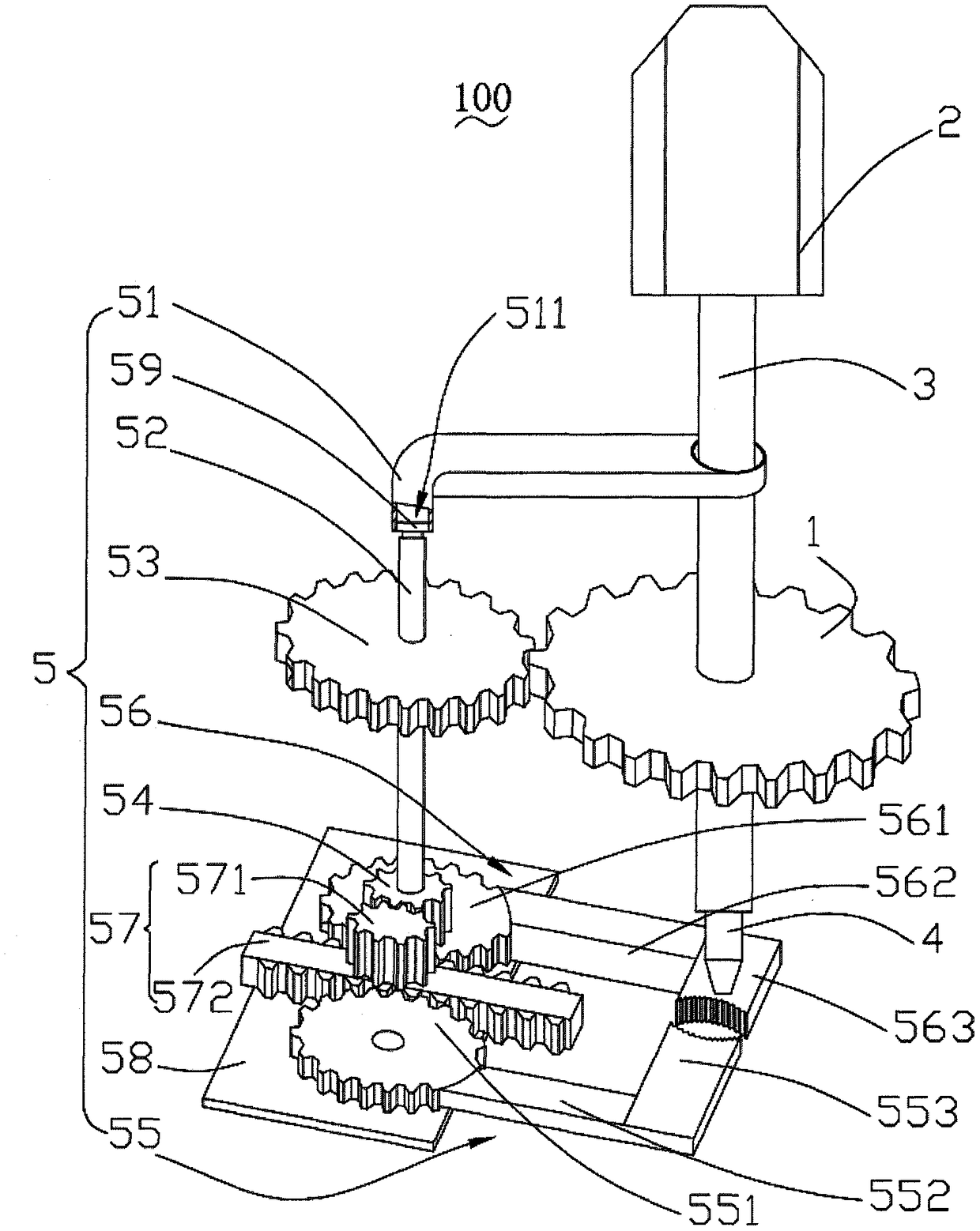
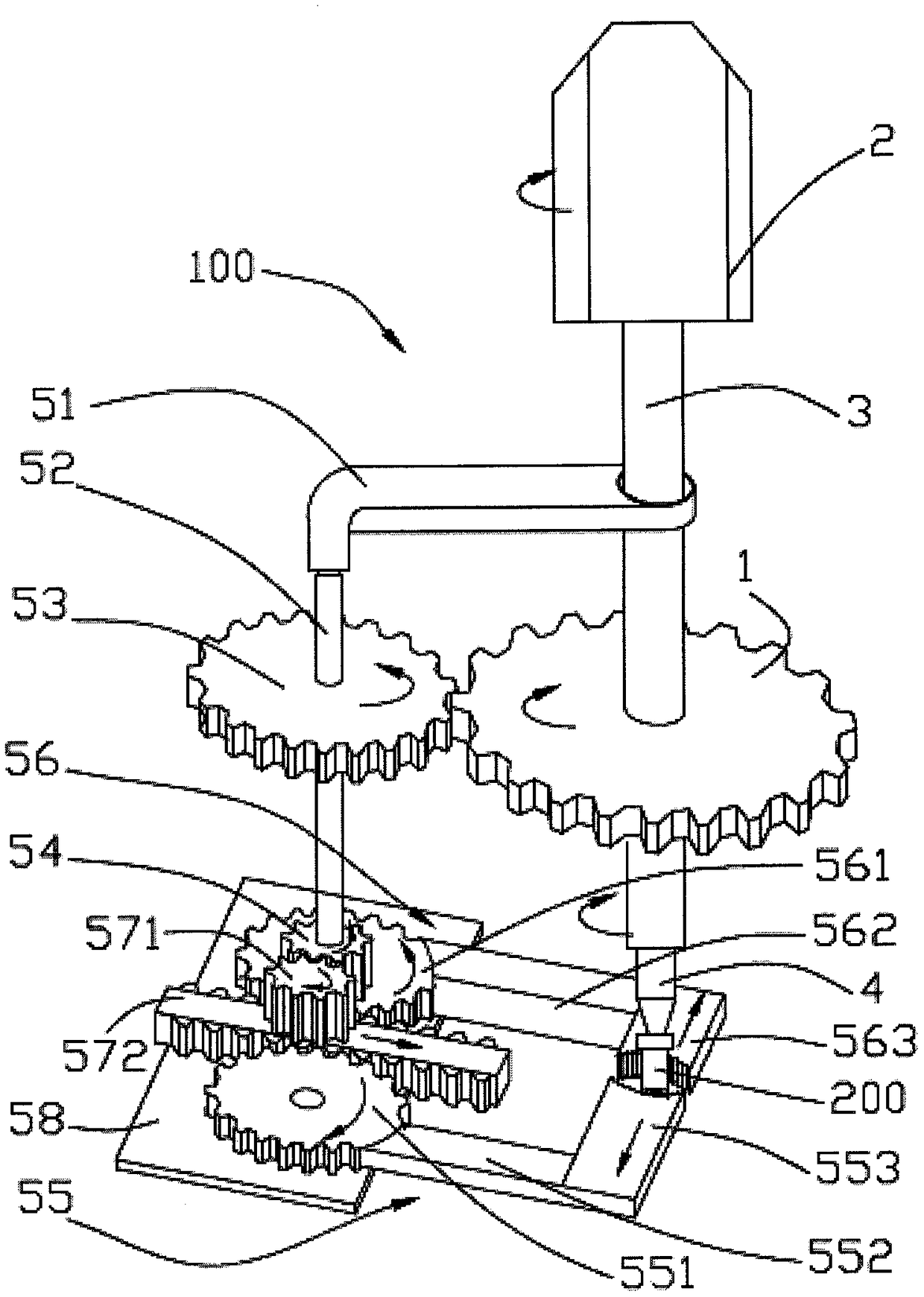
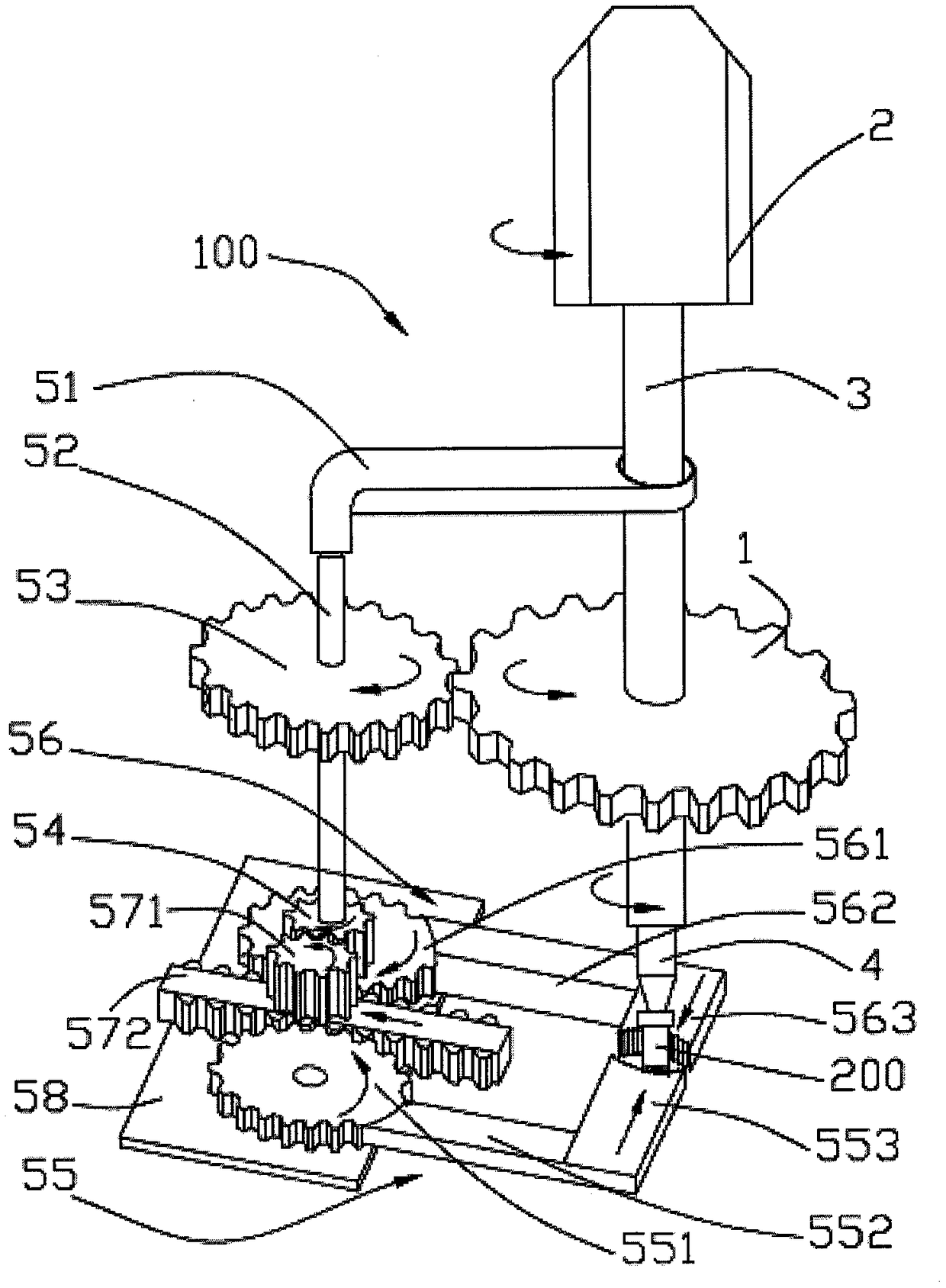
[0024] see figure 1 It is a structural schematic diagram of a screwdriver for orthopedic surgery provided by the present invention. The screwdriver 100 for orthopedic surgery includes a driving wheel 1 , a handle 2 , a knife rod 3 , a knife head 4 and a fixing device 5 .
[0025] The handle 2, the cutter bar 3 and the cutter head 4 are connected in sequence. The handle 2 is covered with an anti-skid layer, which is...
PUM
Abstract
The invention provides a screw driver for an orthopedic surgery. The screw driver for the orthopedic surgery comprises a driving wheel, a handle, a tool bar and a tool bit, wherein the handle, the tool bar and the tool bit are sequentially connected, and the driving wheel is arranged on the tool bar and used for a fixing device for clamping screws. The fixing device comprises a turning bar, a sliding sleeve, a driven wheel, a synchronous wheel, a first clamping device, a second clamping device, a moving device and a fixing plate, wherein the turning bar and the tool bar are parallelly arranged at intervals, one end of the sliding sleeve sleeves the too bar, the other end of the sliding sleeve is pivotally connected with the turning bar, the driven wheel is arranged on the turning bar and engaged with the driving wheel, the synchronous wheel is arranged on the turning bar, the first clamping device and the second clamping device are oppositely arranged, the moving device is arranged between the first clamping device and the second clamping device, and the fixing plate is used for fixing the first clamping device and the second clamping device and can rotate the first clamping device and the second clamping device. Compared with related technology, the screw driver for the orthopedic surgery is convenient to operate, secondary injury to patients is avoided, surgical efficiency is improved, and surgical time is shortened.
Description
technical field [0001] The invention relates to the technical field of medical instruments, in particular to a screwdriver for orthopedic surgery. Background technique [0002] There are as many as millions of cases of surgical internal fixation due to fractures in the world. The internal fixation mainly involves placing some metal materials into the human body, and the cases treated by internal fixation with steel plates need to be replaced by bone nails, steel plates after the broken bones heal. take out. Due to the small size of the screw, when using the current screwdriver for fixation, the position and direction of the screw need to be adjusted with the help of nail holders. When the incision of the surgical site is small, it is inconvenient to use the nail holder to adjust the position of the screw, which brings inconvenience to the medical staff . In addition, the screws are often deformed when subjected to large stresses in the body, which greatly increases the fri...
Claims
Application Information
Patent Timeline
Application Date:The date an application was filed.
Publication Date:The date a patent or application was officially published.
First Publication Date:The earliest publication date of a patent with the same application number.
Issue Date:Publication date of the patent grant document.
PCT Entry Date:The Entry date of PCT National Phase.
Estimated Expiry Date:The statutory expiry date of a patent right according to the Patent Law, and it is the longest term of protection that the patent right can achieve without the termination of the patent right due to other reasons(Term extension factor has been taken into account ).
Invalid Date:Actual expiry date is based on effective date or publication date of legal transaction data of invalid patent.