Rubbing blade, rubbing impeller and pure metallurgical coke breeze forming raw material rubbing machine
A blade and impeller technology, applied in the direction of fuel, mixer, solid fuel, etc., can solve the problems of low stirring speed, uneven mixing, poor wear resistance, etc. long effect
- Summary
- Abstract
- Description
- Claims
- Application Information
AI Technical Summary
Problems solved by technology
Method used
Image
Examples
Embodiment 1
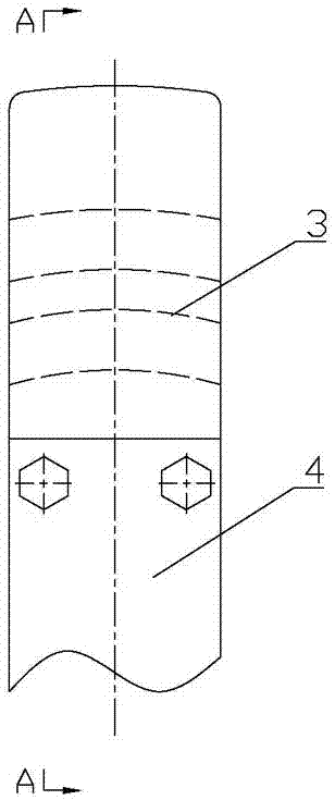
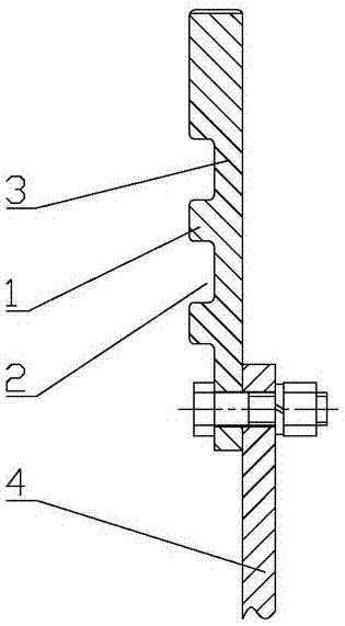
[0041] Embodiment one: as attached Figures 1 to 9 As shown, the kneading blade includes the blade body, at least two kneading ribs 1 are distributed from top to bottom on the upper rear side of the blade body, and kneading concaves are formed between each two kneading kneading ribs 1 adjacent up and down. Slot 2. When in use, this embodiment can be directly or indirectly fixedly installed on the outside of the rotating shaft 30 through other existing known connectors, so that the blade body can rotate with the rotating shaft 30, and in the process of its rotation, it can not only turn over Stirring the material can also make the material go through more rubbing, collision, rolling, friction, shearing, extrusion, exchange, and rubbing again in the same space through the joint action of the rubbing rib 1 and the rubbing groove 2. So that the stirring and mixing of materials can be more uniform and sufficient, especially when it is used for kneading operation of coke powder mix...
Embodiment 2
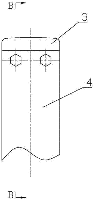
[0045] Embodiment two: as attached Figures 1 to 9 As shown, the blade body includes a wear-resistant liner 3 and a blade base 4. The upper part of the blade base 4 is located on the lower front side of the wear-resistant liner 3, and the wear-resistant liner 3 and the blade base 4 are fixedly installed together by bolts. On the rear side of the wear-resistant liner 3, kneading ribs 1 that are distributed up and down at intervals are fixed. Since the kneading convex ribs 1 are evenly distributed on the wear-resistant liner 3, and the wear-resistant liner 3 is the main active part, its wear rate is relatively high, and it is a vulnerable part, so the wear-resistant liner 3 is connected with the blade base 4 by bolts. Fixing together can also make the replacement of the wear-resistant liner 3 more convenient and quick, and prolong the service life of the blade matrix 4 .
Embodiment 3
[0046] Embodiment three: as attached Figures 1 to 9 As shown, the blade body includes a wear-resistant liner 3 and a blade base 4. The wear-resistant liner 3 is in an inverted L shape, and the opening of the wear-resistant liner 3 is stuck on the upper rear side of the blade base 4. The wear-resistant liner 3 and The blade base 4 is fixed and installed together by bolt connection, and the back side of the blade base 4 corresponding to the lower position of the wear-resistant liner 3 is fixed with kneading ribs 1 distributed up and down at intervals, and the wear-resistant liner 3 is the kneading rib 1 at the top. Edge 1. According to requirements, there is a distance between the wear-resistant liner 3 and the adjacent kneading ribs 1 below it. By adding a wear-resistant liner 3 on the rear side of the upper part of the blade base 4, the wear-resistant liner 3 can be made to be the main rib. Since the main rib is the main working area, its wear rate will be higher than other ...
PUM
| Property | Measurement | Unit |
|---|---|---|
| width | aaaaa | aaaaa |
Abstract
Description
Claims
Application Information
 - R&D
- Intellectual Property
- Life Sciences
- Materials
- Tech Scout
- Unparalleled Data Quality
- Higher Quality Content
- 60% Fewer Hallucinations
Browse by: Latest US Patents, China's latest patents, Technical Efficacy Thesaurus, Application Domain, Technology Topic, Popular Technical Reports.
© 2025 PatSnap. All rights reserved.Legal|Privacy policy|Modern Slavery Act Transparency Statement|Sitemap|About US| Contact US: help@patsnap.com


