A cooling method for a planetary pipe mill

A technology of planetary pipe rolling mill and cooling method, which is applied in the direction of rolling, metal rolling, metal rolling, etc., can solve the problems of low cooling efficiency, insufficient cooling intensity, and cooling liquid injection, etc., to improve cooling efficiency and increase production , the effect of improving the service life

Active Publication Date: 2019-05-17
JIANGSU XINGRONG HI TECH
View PDF13 Cites 0 Cited by
  • Summary
  • Abstract
  • Description
  • Claims
  • Application Information

AI Technical Summary

Problems solved by technology

Increasing the cooling water flow rate and pressure also makes it difficult to inject more coolant into the required area. The cooling efficiency of the static spray plate or nozzle in the prior art is low, and the cooling intensity is not enough to further increase the output of the rolling mill.

Method used


Image

  • A cooling method for a planetary pipe mill
  • A cooling method for a planetary pipe mill
  • A cooling method for a planetary pipe mill

Examples


Embodiment 1

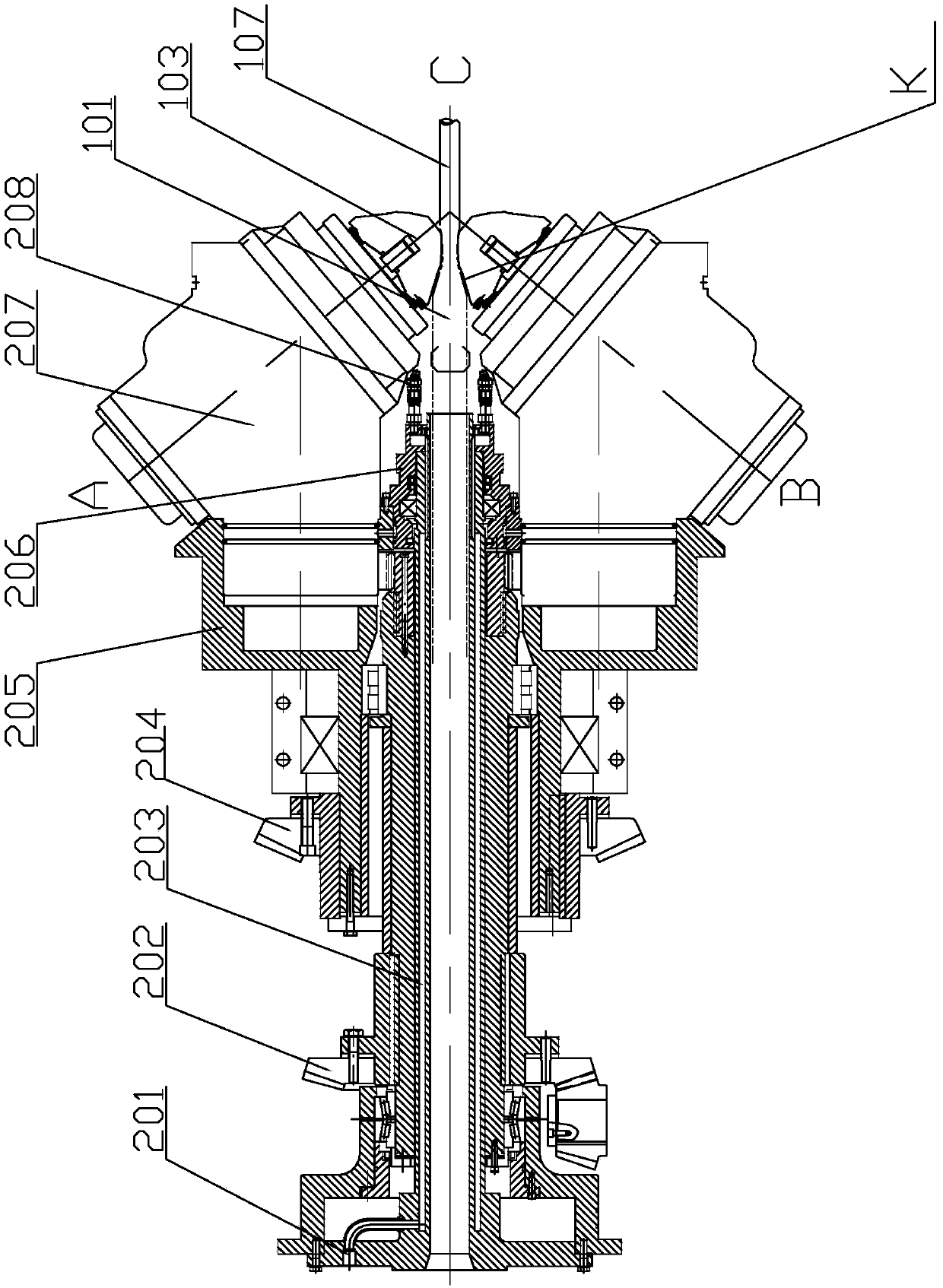
[0037] figure 1 A schematic diagram of a device for applying the method of the present invention is given.

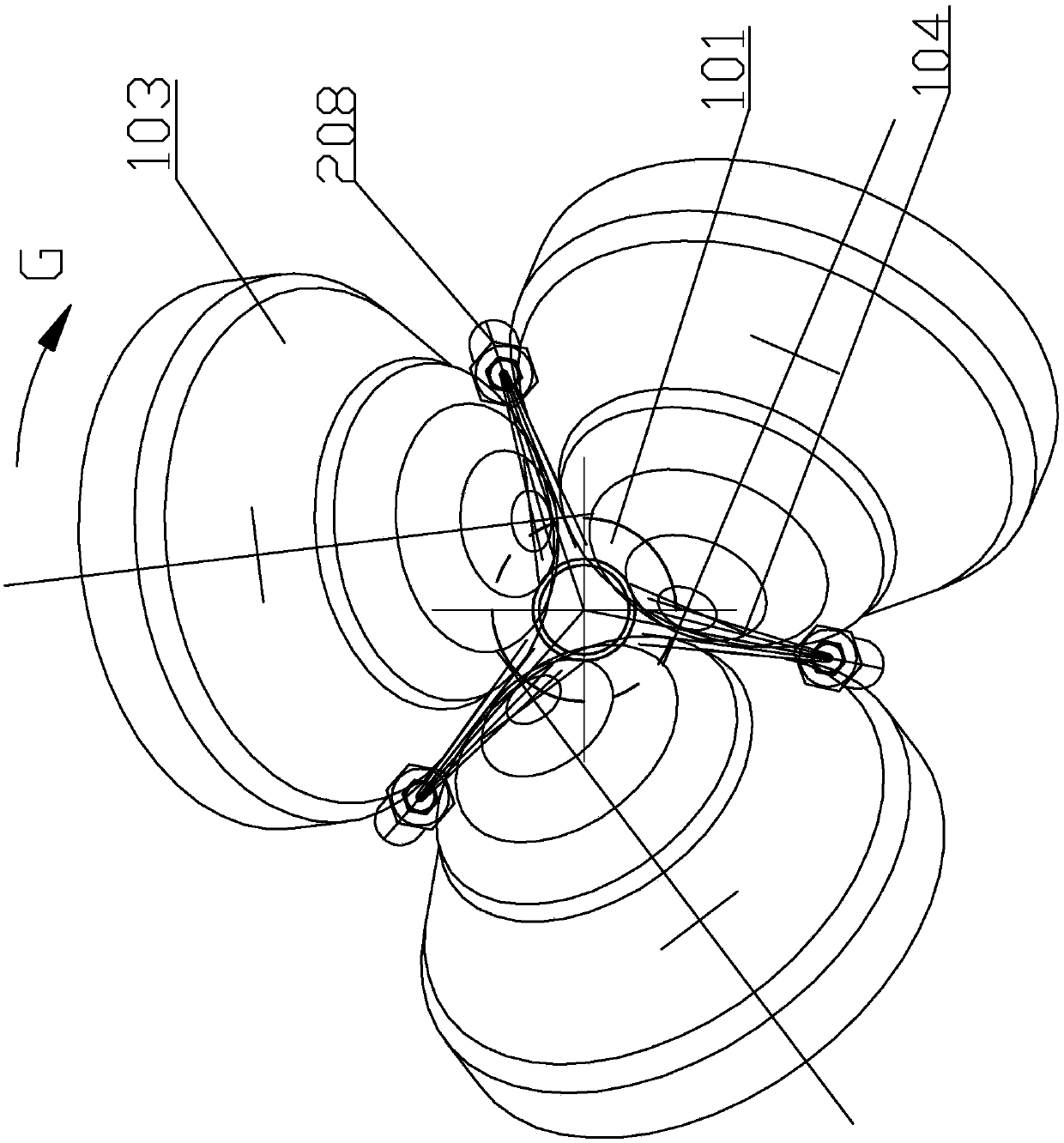
[0038] Depend on figure 1It can be seen that the main and auxiliary motors (not shown in the figure) of the planetary pipe mill respectively drive the main bevel gear 204 and the auxiliary bevel gear 202 to rotate, and the main bevel gear 204 drives the rotary body 205 to rotate. Three roll stands 207 are housed on the rotary body 205, and roll 103 is housed on the roll stand 207. During pipe rolling, driven by the main and auxiliary motors, the rotator 205, the roll stand 207 and the rolls 103 revolve around the rolling center line C-C. At the same time, the roll 103 also rotates on its own axis AC or BC.

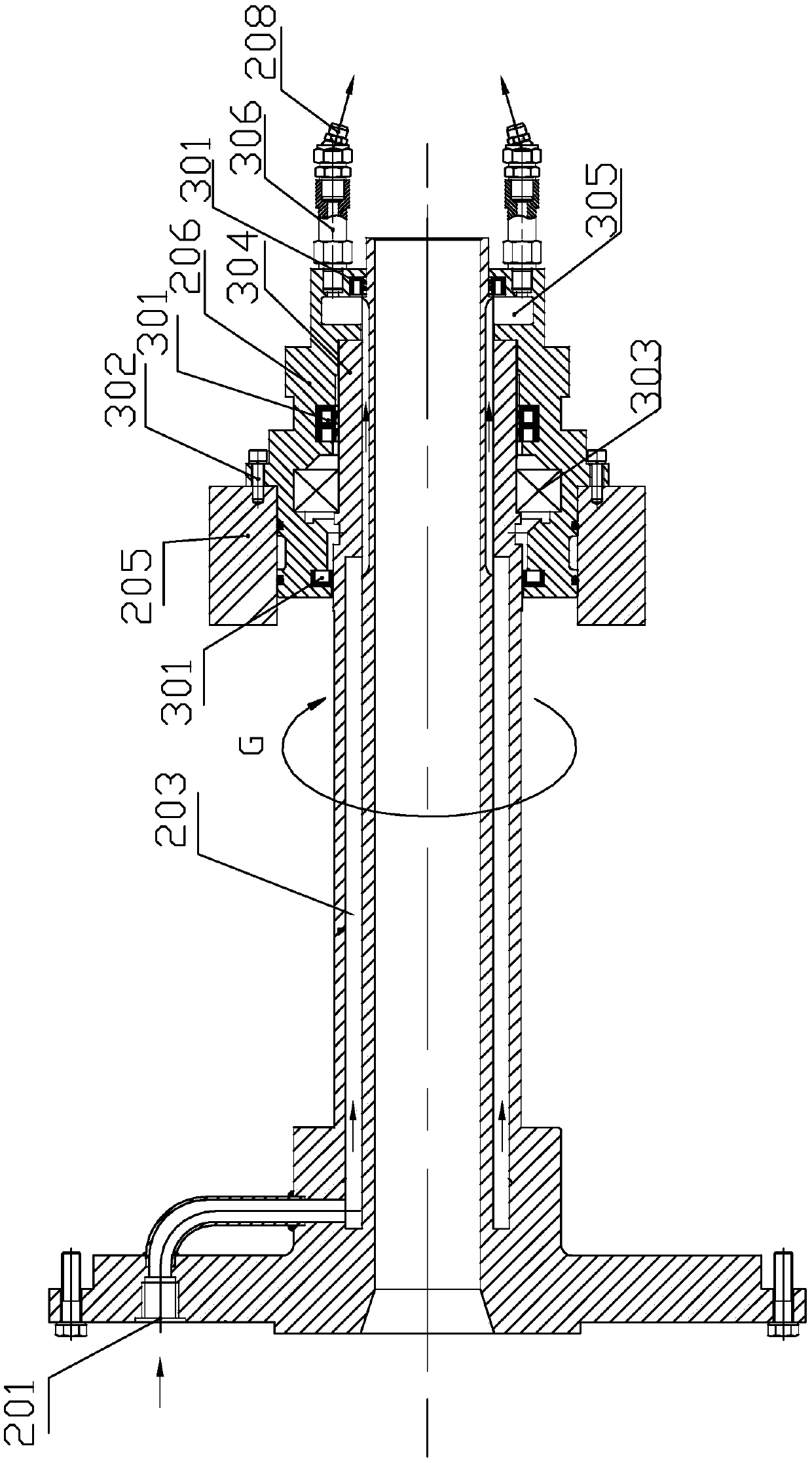
[0039] figure 1 It can also be seen that the cooling water enters from the cooling water inlet 201 at the entrance of the rolling mill, enters the water spray assembly 1 206 through the water jacket 1 203 of the central pipe of the rolling mill, and is connec...

Embodiment 2

[0047] Figure 4 A schematic diagram of Embodiment 2 is given. The difference from the first embodiment is that in the second embodiment, the rolling deformation zone K and / or the roll 103 are cooled by rotation at the exit part of the rolling mill.

[0048] The outlet nozzle seat 410 is fixed on the protective cover (not shown in the figure) of the rolling mill. The protective cover of the mill is fixed to the ground. The second water spray assembly 405 is installed on the outlet nozzle seat 410 through the second bearing 404 . The right side of the water spray assembly 2 405 is connected with the water inlet ring 409, the water inlet ring 409 is provided with a cooling water inlet 2 407, the cooling water inlet 407 is connected with the water jacket 2 406 and the sealing water chamber 2 in the water spray assembly 2 405 403 is connected. The left side of the water spray assembly 2 405 is a rotating spray plate 411, and a group of small holes are opened on the rotary spra...


PUM


Abstract

The invention relates to a cooling method of a planetary rolling mill, and the cooling method is used for cooing the planetary rolling mill. The cooling method of the planetary rolling mill adopts the technical scheme of comprising cooling water nozzles (208), rollers (103), a revolved body (205), a rolling center line (C-C) and a rolling deformation zone (K); and the technical scheme is characterized in that when the rolling mill works, the cooling water nozzles (208) and the revolved body (205) rotate synchronously around the rolling center line (C-C), the cooling water nozzles (208) spray cooling water to the rolling deformation zone (K), and / or the cooling water nozzles (208) spray the cooling water to the rollers (103). After the technical scheme is adopted, the cooling effect of the deformation zone and the rollers of the planetary rolling mill can be remarkably improved, and the production efficiency of the planetary rolling mill can be improved.

Description

technical field [0001] The invention relates to a cooling method for a planetary pipe rolling mill, which is mainly used for cooling the rolling deformation zone of the planetary pipe rolling mill, and belongs to the technical field of metal pipe processing methods. Background technique [0002] The planetary rolling mill is a kind of skew rolling pipe mill for metal pipes with known technology. The planetary rolling mill is mainly driven by main and auxiliary motors. During rolling, the main and auxiliary motors drive the rolls installed on the rotating body of the rolling mill to revolve around the rolling center line, and at the same time, the rolls rotate around their respective axes. During the rolling process, through the adjustment of the speed of the main and auxiliary motors, the rolled pipe does not rotate after it exits the rolling mill, so that super long pipes can be rolled. Patent No. US6792781, the rolling mill invented by EP2116312 also belongs to this type...

Claims


Application Information

Patent Timeline
Patent Type & Authority Patents(China)
IPC IPC(8): B21B27/10
CPCB21B27/10B21B2027/103
Inventor 沈思平王月彬
Owner JIANGSU XINGRONG HI TECH
Why Eureka
Try Eureka