Injection moulding die used for automotive sealing strip

A technology for automobile sealing strips and injection molds, which is applied to household appliances, other household appliances, applications, etc., can solve the problems of high yield and low yield, and achieve the effect of low cost, small error, and solving accumulated tolerances.

Pending Publication Date: 2017-08-18
NINGHAI HESHI PLASTIC CO LTD
View PDF3 Cites 1 Cited by
  • Summary
  • Abstract
  • Description
  • Claims
  • Application Information

AI Technical Summary

Problems solved by technology

[0005] After adopting the above structure, the present invention has the following advantages compared with the prior art: the positioning method of the product body in the mold is technologically innovated, and the positioning is changed from the original rear punching position to the front sawing surface in the mold for positioning, effectively It solves the problem of low yield caused by excessive accumulated tolerances. Without affecting the product appearance requirements and product structure, it greatly improves production efficiency and saves production costs. When placing the sealing strip on the lower formwork for encapsulation , Use the positioning block to position the sealing strip, so that the size of the gap between the oblique slider and the sealing strip is accurate, effectively solve the accumulated tolerance, ensure the accuracy of the lagging, the error is small, and the gap between the oblique slider and the sealing strip It is used to fill the lagging material, and at the same time when the mold is closed, the positioning block is separated from the sealing strip, that is, the positioning block is reset, and the inclined slider moves to the front end of the sealing strip, and the lagging can be performed, which can effectively eliminate the punching tolerance and increase the yield rate. High, simple structure, low cost, non-interference between positioning action and rubber action, high reliability

Method used


Image

  • Injection moulding die used for automotive sealing strip
  • Injection moulding die used for automotive sealing strip
  • Injection moulding die used for automotive sealing strip

Examples


Embodiment Construction

[0027] The present invention will be further described below in conjunction with the accompanying drawings and specific embodiments.

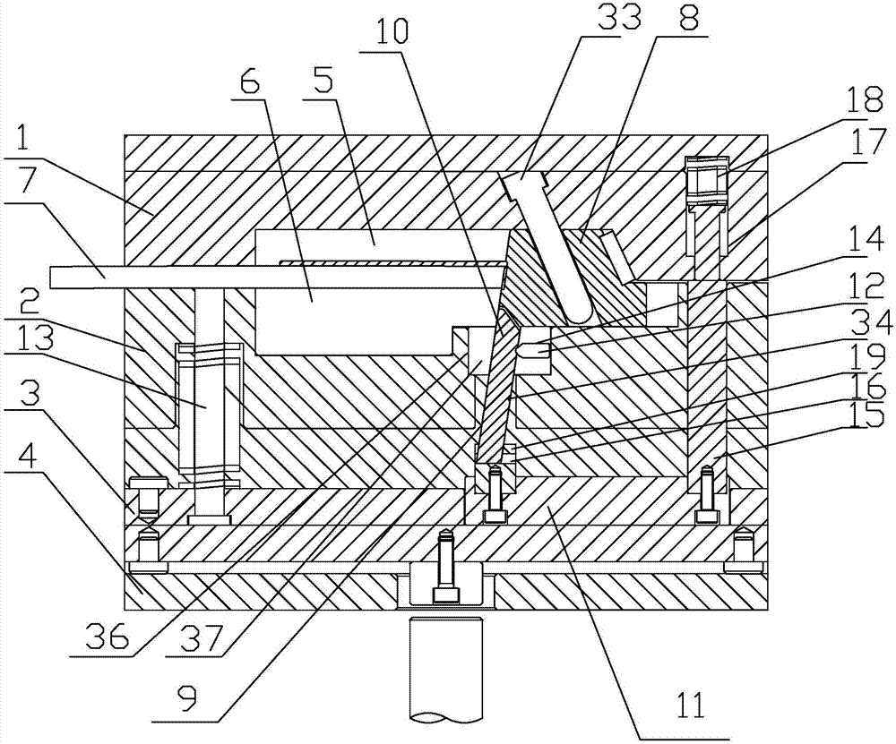
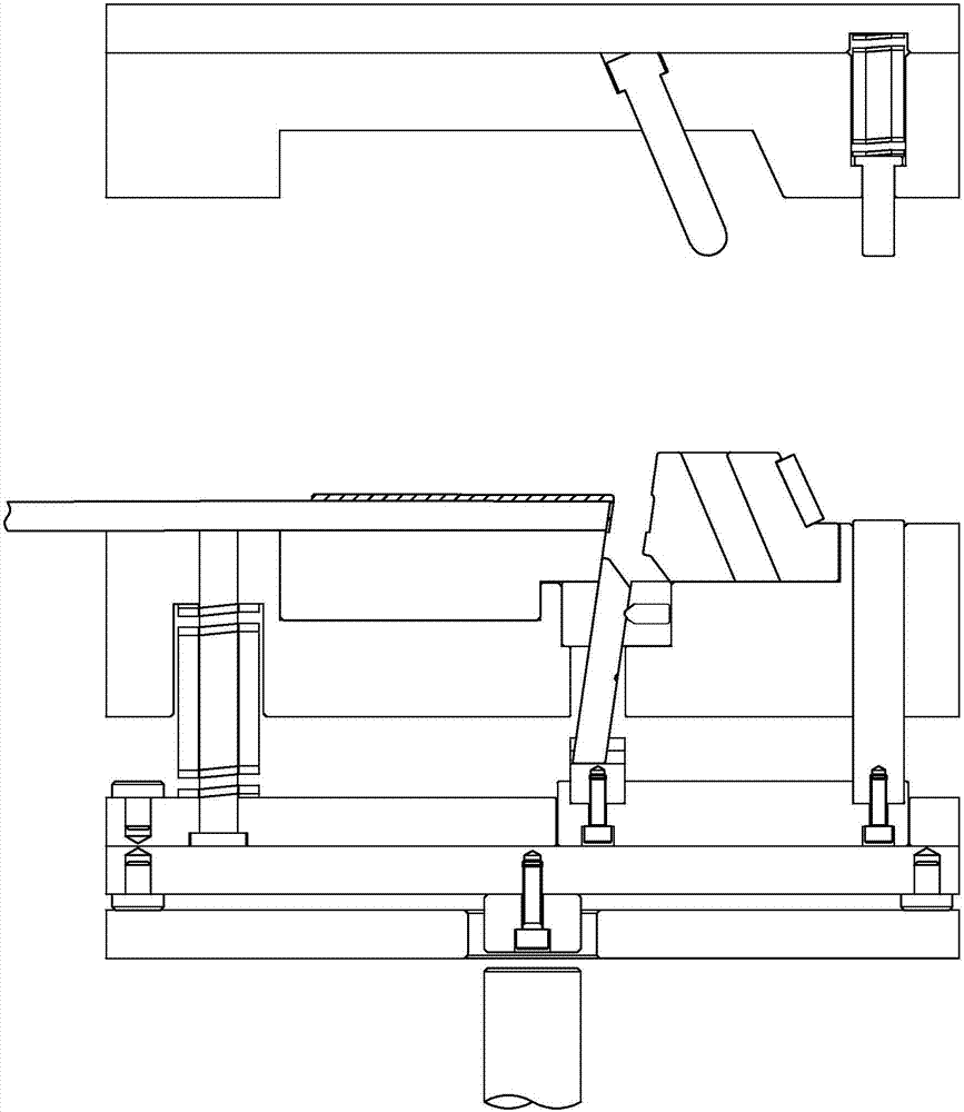
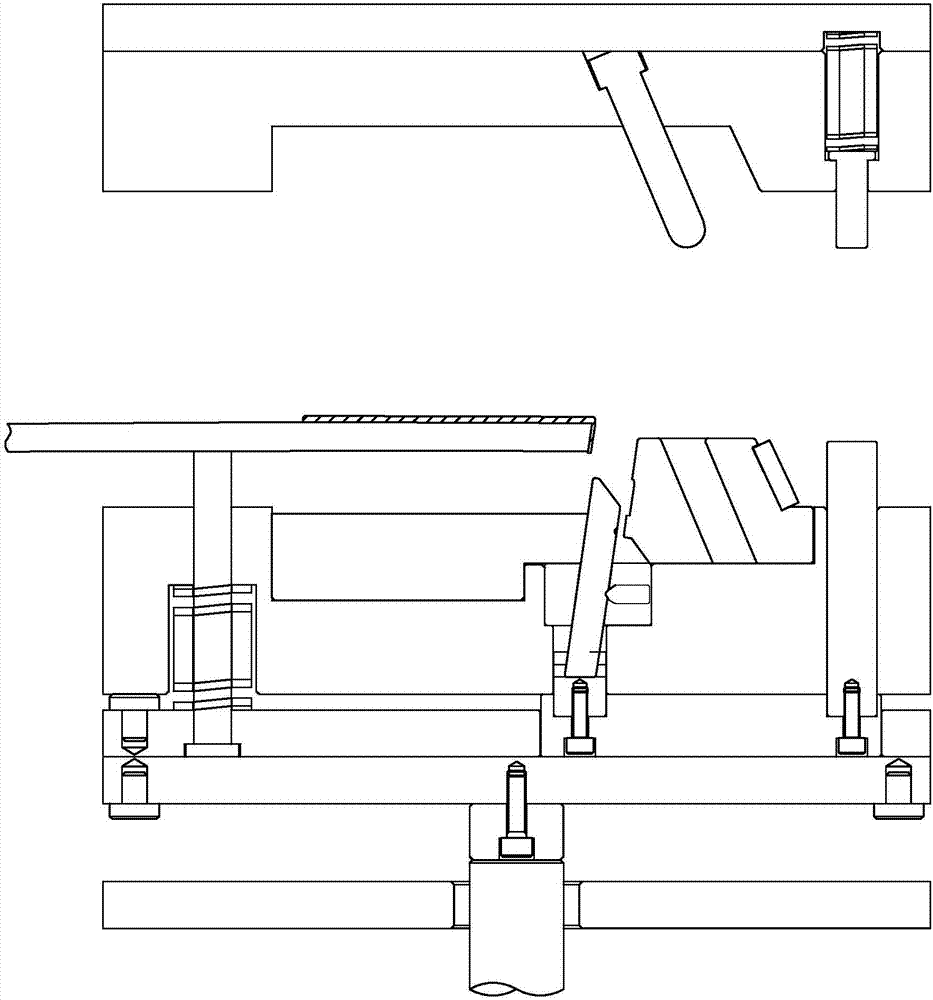
[0028]As shown in the figure, the present invention provides an injection mold for automotive weather strips, including an upper template 1, a lower template 2, a push plate 3, a base plate 4 and a seal 7, and the push plate 3 is located on the base plate 4 Above, the lower template 2 is located between the upper template 1 and the push plate 3, the upper mold core 5 is arranged below the upper template 1, and the lower mold core 6 is arranged above the lower template 2, and the The lower template 2 is provided with an oblique slider 8 for forming the front end of the sealing strip 7 and a slider 22 for forming the inner side of the front end of the sealing strip 7. The upper template 1 is provided with an oblique slide The oblique guide column 33 that slides and fits with the block 8, and the type that wraps the inner surface and the front end...


PUM


Abstract

The invention discloses an injection moulding die used for an automotive sealing strip. The injection moulding die comprises an upper die plate (1), a lower die plate (2), an ejection plate (3), a base plate (4) and a sealing strip (7), wherein the ejection plate (3) is located on the base plate (4); the lower die plate (2) is located between the upper die plate (1) and the ejection plate (3); an upper mandrel (5) is arranged below the upper die plate (1); a lower mandrel (6) is arranged above the lower die plate (2); an oblique sliding block (8) used for moulding the front end surface rubber coating part of the sealing strip (7) and a sliding block (22) used for moulding the front end inner side surface rubber coating part of the sealing strip (7) are arranged on the lower die plate (2); and an oblique guide post (33) which is in sliding match with the oblique sliding block (8) is arranged on the upper die plate (1). The injection moulding die used for the automotive sealing strip has the beneficial effects that punching tolerance can be effectively eradicated, so that the yield is high, and cost is low.

Description

technical field [0001] The invention relates to the technical field of molds, in particular to an injection mold for automobile weather strips. Background technique [0002] Automobile sealing strip is one of the important parts of automobiles. It is widely used in doors, windows, body, seats, sunroof, engine box and trunk, etc. It has waterproof, sealing, sound insulation, dustproof, antifreeze, shock absorption, The important role of heat preservation and energy saving. The water-cut strip is the rubber sealing strip inside the window groove, which is between the window glass and the door frame. The front part of the water-cut strip needs to be glued on the injection molding machine. Water-cut strips are positioned. According to the existing technology, the positioning method of the product body in the mold is the positioning of the rear punching position. Since the water-cut strips have to go through multiple processes in the early stage, the cumulative tolerance value is...

Claims


Application Information

Patent Timeline
Patent Type & Authority Applications(China)
IPC IPC(8): B29C45/14B29C45/40B29L31/26
CPCB29C45/14065B29C45/4005B29L2031/265
Inventor 任典兴葛永峰杨慧峰颜文斌
Owner NINGHAI HESHI PLASTIC CO LTD
Why Eureka
Try Eureka