
Large-load rope climbing mechanism based on special-shaped chain wheel transmission

A sprocket drive, large load technology, applied in the direction of transmission chain, transmission device, belt/chain/gear, etc., can solve the problems of small lifting heavy load, easy to be worn by rope bending, poor safety and reliability, etc. Operation lift and drop effect, light weight, smooth motion effect

Active Publication Date: 2017-08-18
HARBIN INST OF TECH
View PDF5 Cites 13 Cited by
  • Summary
  • Abstract
  • Description
  • Claims
  • Application Information

AI Technical Summary

Problems solved by technology

[0004] The purpose of the present invention is to solve the problem that the existing rope climbing mechanism has a small weight and a narrow range for lifting heavy loads, poor safety and reliability during continuous lifting and lowering work, in addition, the contact between the rope and other components is point contact, and the rope is easy to bend. The problem of being damaged by wear and tear, and then provide a large-load rope climbing mechanism based on special-shaped sprocket drive

Method used


Image

  • Large-load rope climbing mechanism based on special-shaped chain wheel transmission
  • Large-load rope climbing mechanism based on special-shaped chain wheel transmission
  • Large-load rope climbing mechanism based on special-shaped chain wheel transmission

Examples


specific Embodiment approach 1

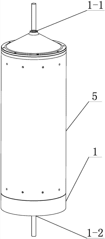
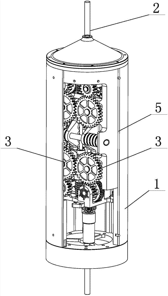
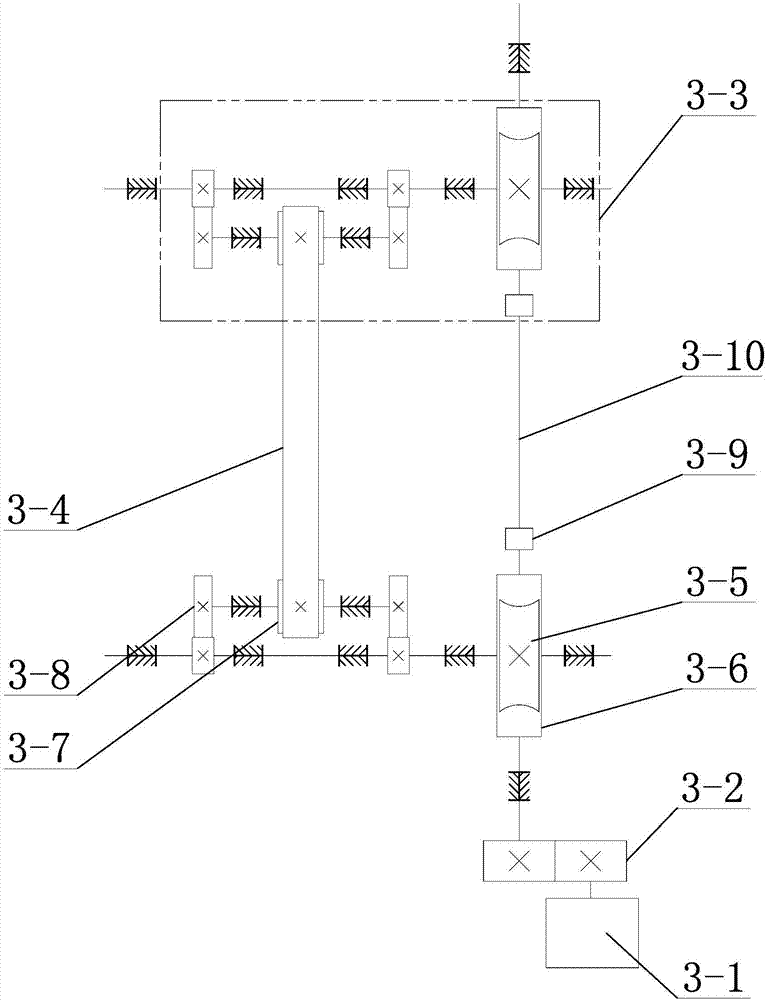
[0025] Specific implementation mode one: combine figure 1 , figure 2 , image 3 , Figure 4 , Figure 5 , Image 6 , Figure 7 , Figure 8 , Figure 9 with Figure 10 Describe this embodiment. This embodiment includes a main body support 1, a rope 2 and two sets of transmission systems 3. The two sets of transmission systems 3 are arranged side by side inside the main body support 1. The two sets of transmission systems 3 have the same structure. The transmission system 3 includes a motor 3-1, a first gear adjustment assembly 3-2, a special-shaped chain 3-4 and two sprocket assemblies 3-3, and the two sprocket assemblies 3-3 are along the sides of the main body support 1. The length direction is juxtaposed, and each sprocket assembly 3-3 includes a worm gear 3-5, a worm screw 3-6, a special-shaped sprocket 3-7 and two second gear adjustment assemblies 3-8, and the worm gear 3-5 and The worms 3-6 are meshed, the two second gear adjustment assemblies 3-8 are coaxially ...

specific Embodiment approach 2

[0029] Specific implementation mode two: combination figure 2 Describe this embodiment. In this embodiment, the main body support 1 is arranged vertically. The top of the main body support 1 is processed with an upper opening 1-1, and the bottom of the main body support 1 is processed with a lower opening 1-2. One end of the rope 2 passes through the upper opening 1-1, and the other end of the rope 2 passes through the gap between the two special-shaped chains 3-4 and the lower opening 1-2 at the bottom of the main body support 1 in turn, so Said rope 2 reciprocates between the upper port 1-1 and the lower port 1-2 driven by two special-shaped chains 3-4. Other unmentioned structures and connections are the same as those in the first embodiment.

specific Embodiment approach 3

[0030] Specific implementation mode three: combination Figure 2 to Figure 9Describe this embodiment, in this embodiment, each special-shaped chain 3-4 is made up of a plurality of chain links 3-4-1 and a plurality of connecting pieces 3-4-2, and each chain link 3-4-1 is provided with Two connecting shafts 3-4-3, the outer end surface of each chain link 3-4-1 is processed with a placement groove 3-4-4 matched with the rope 2, a plurality of chain links 3-4-1 A rope clamping channel is formed between the placement grooves 3-4-4, and each chain link 3-4-1 is connected to the two adjacent chain links 3-4-1 through four connecting pieces 3-4-2. connection, the ends of the two connecting shafts 3-4-3 on each chain link 3-4-1 are respectively provided with a connecting piece 3-4-2, and the ends of each connecting shaft 3-4-3 It is hinged to the connecting shaft 3-4-3 on the adjacent chain link 3-4-1 through its corresponding connecting piece 3-4-2.

[0031] In this embodiment, the...


PUM


Abstract

The invention relates to a large-load rope climbing mechanism, in particular to a large-load rope climbing mechanism based on special-shaped chain wheel transmission. Existing rope climbing mechanisms are small in lifting weight load weight and range and poor in safety and reliability during continuous lifting and falling work, additionally, contact between a rope and other components is point contact, and meanwhile, the rope is bent and prone to being damaged due to abrasion. The large-load rope climbing mechanism comprises a main supporting part, a rope and two transmission systems. The two transmission systems are arranged in the main supporting part. Each transmission system comprises a motor, a first gear adjustment assembly, a special-shaped chain and two chain wheel assemblies, wherein worm wheels are engaged with worms; every two second gear adjustment assemblies are coaxially connected with the corresponding work wheel; a special-shaped chain wheel is arranged between every two second gear adjustment assemblies; every two special-shaped chain wheels are connected through the special-shaped chain; every two worms are coaxially connected; and the motor is connected with any worm through the first gear adjustment assembly. A rope is clamped between the two special-shaped chains in the two transmission systems. The large-load rope climbing mechanism is used for lifting and releasing weights.

Description

technical field [0001] The invention relates to a large-load rope climbing mechanism based on special-shaped sprocket transmission, which belongs to the technical field of special robots. Background technique [0002] Rope climbing robot, as an auxiliary motion carrier tool, is used in individual operations, mountain climbing, rapid rescue, earthquake and other emergency rescue, installation of top parts of high-rise buildings, wall construction, cable-stayed bridge cable flaw detection maintenance, pipeline monitoring and maintenance, tunnels, etc. Excavation and many other fields have a wide range of applications. The large-load rope climbing mechanism is responsible for the important tasks of controlling the lifting, lowering, stopping and controlling the lowering speed of the large load. At the same time, for the tactical lifter, its maneuverability must be fully guaranteed to meet the requirements for rapid movement of individual soldiers. [0003] The key technology ...

Claims


Application Information

Patent Timeline
IPC IPC(8): B66F19/00F16H37/04F16G13/07
CPCB66F19/00F16G13/07F16H37/04
Inventor 郭宏伟邓宗全吴英辉田志东刘荣强
Owner HARBIN INST OF TECH
Learn More