Evaporation crucible and evaporation equipment

A technology of evaporation and crucible, which is applied in the field of equipment manufacturing, can solve the problems of unstable evaporation rate and poor film quality of evaporation crucible, and achieve the effects of reducing deterioration, improving stability and improving quality

Inactive Publication Date: 2017-08-18
BOE TECH GRP CO LTD
View PDF7 Cites 9 Cited by
  • Summary
  • Abstract
  • Description
  • Claims
  • Application Information

AI Technical Summary

Problems solved by technology

[0004] Aiming at the above-mentioned deficiencies in the prior art, the present invention provides an evaporation crucible and evaporation equipment, which are used to at least partially solve the problems of unstable evaporation rate and poor film quality of the existing evaporation crucible

Method used


Image

  • Evaporation crucible and evaporation equipment
  • Evaporation crucible and evaporation equipment
  • Evaporation crucible and evaporation equipment

Examples


Embodiment 1

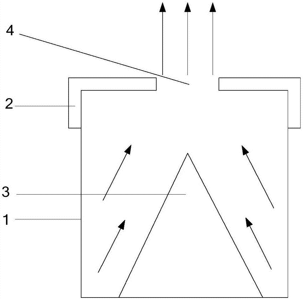
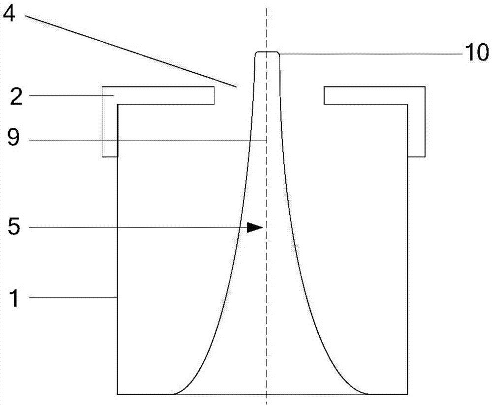
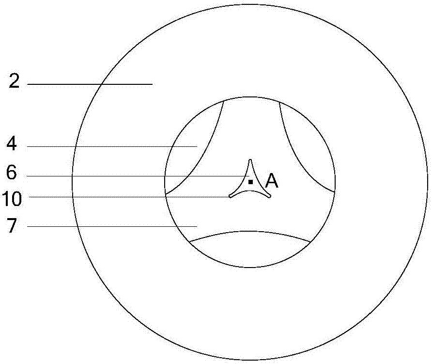
[0031] Embodiment 1 of the present invention provides an evaporation crucible, combined with figure 2 , image 3 and Figure 4 As shown, the evaporation crucible includes a body 1, a cover body 2 and a heat conduction column 5. The body 1 is a hollow chamber for accommodating evaporation materials. Preferably, the shape of the body 1 is a circular truncated or cylindrical, circular truncated or cylindrical The side of the body 1 is an arc surface, which is not easy to adhere to the vapor deposition material. In this embodiment, the shape of the body 1 is a cylinder as an example for illustration. The cover body 2 is arranged on the top of the body 1 , and the cover body 2 has an opening 4 . The heat conduction column 5 is arranged on the bottom wall of the body 1 , and the top end of the heat conduction column 5 is located at the position of the opening 4 . Specifically, the orthographic projection of the top of the heat conduction column 5 on the bottom wall of the body 1 ...

Embodiment 2

[0046] Embodiment 2 of the present invention provides an evaporation equipment, such as Figure 6 As shown, the evaporation equipment includes a heating device 11 and the above-mentioned evaporation crucible, and the heating device 11 is used to heat the evaporation crucible.

[0047] Such as Figure 6 As shown, preferably, the heat conduction column 5 can be integrally formed with the bottom wall of the body 1, that is, the position corresponding to the heat conduction column 5 on the bottom wall of the body 1 is recessed toward the direction of the cover body 2, so that the side wall of the heat conduction column 5 and the The top wall forms an accommodating space 13 . The heating device 11 can be located in the accommodating space 13, and the heating device 11 heats the steamer crucible from the accommodating space 13, that is, from the middle of the body 1, and the heating uniformity is better, which is beneficial to improving the uniformity of evaporation of the evaporat...

Embodiment 3

[0051] Embodiment 3 of the present invention provides a kind of vapor deposition equipment, such as Figure 7 As shown, the difference between the evaporation equipment provided in Example 3 and the evaporation equipment provided in Example 2 is that: the thermal conduction column 5 and the bottom wall of the body 1 do not form an accommodating space 13, and the heating device 11 is located below the evaporation crucible .

[0052] Specifically, such as Figure 7 As shown, the heat conduction column 5 is arranged on the bottom wall of the body 1 and is located inside the evaporation crucible, and the heating device 11 is located below the bottom wall of the body 1 for heating the body 1 .

[0053] It should be noted that, compared with embodiment 2 and embodiment 3, embodiment 2 is a preferred implementation manner. In Example 2, the heating device 11 is located in the accommodating space 13 . Compared with the heating device 11 located below the evaporation crucible in Exam...


PUM


Abstract

The invention provides an evaporation crucible and evaporation equipment. The evaporation crucible comprises a body and a cover with an opening. The cover is arranged on the top of the body. A heat conducting column is arranged on the bottom wall of the body. The top end of the heat conducting column is located at the opening position. In the evaporation process, the heat conducting column can conduct heat to evaporation materials around the heat conducting column, and the evaporation materials in the body are heated and evaporated. Compared with a manner that heating is conducted only through the outer wall of a body, the evaporation uniformity of the evaporation materials is better, deterioration of the evaporation materials in the body can be reduced, and accordingly, the film forming quality of the vacuum evaporation technology is improved. Meanwhile, the distance between the side wall of the heat conducting column and the side wall of the opening is short, the heat conducting column can conduct enough heat to the side wall of the opening, the temperature of the side wall of the opening is high, and therefore the evaporation materials can be prevented from being condensed and stacked on the side wall of the opening, and accordingly stability of the evaporation rate of the evaporation materials is improved.

Description

technical field [0001] The invention relates to the field of equipment manufacturing, in particular to an evaporation crucible and evaporation equipment. Background technique [0002] Organic light-emitting diode (Organic Light-Emitting Diode, OLED) display panel has gradually received widespread attention due to its advantages of high color gamut, thin thickness and bendability. Especially curved OLED and flexible OLED are favored by many users for their unique performance and excellent user experience. Vacuum evaporation is the main process used to prepare the organic light-emitting layer in the OLED manufacturing process. Vacuum evaporation is to heat the organic light-emitting material in a certain vacuum environment, so that the organic light-emitting material evaporates and condenses on the surface of the substrate to form a corresponding film. The evaporation crucible is a key component of the vacuum evaporation process, such as figure 1 As shown, the existing evapo...

Claims


Application Information

Patent Timeline
Patent Type & Authority Applications(China)
IPC IPC(8): C23C14/24
CPCC23C14/243
Inventor 罗程远申永奇
Owner BOE TECH GRP CO LTD
Why Eureka
Try Eureka