Supercharge Your Innovation With Domain-Expert AI Agents!

Heat energy utilizing system and power station

A technology of heat energy and heat source, applied in machines/engines, steam engines, mechanical equipment, etc., to solve problems such as heat waste

Pending Publication Date: 2017-08-18
翁志远
View PDF8 Cites 0 Cited by
  • Summary
  • Abstract
  • Description
  • Claims
  • Application Information

AI Technical Summary

Problems solved by technology

[0004] The purpose of the present invention is to provide a thermal energy utilization system to solve the technical problem of a large amount of waste of heat in heat source pipelines such as boiler flues existing in the prior art
[0005] The purpose of the present invention is also to provide a power station to solve the technical problem of a large waste of heat in heat source pipelines such as boiler flues existing in the prior art

Method used


Image

  • Heat energy utilizing system and power station
  • Heat energy utilizing system and power station
  • Heat energy utilizing system and power station

Examples


Embodiment 1

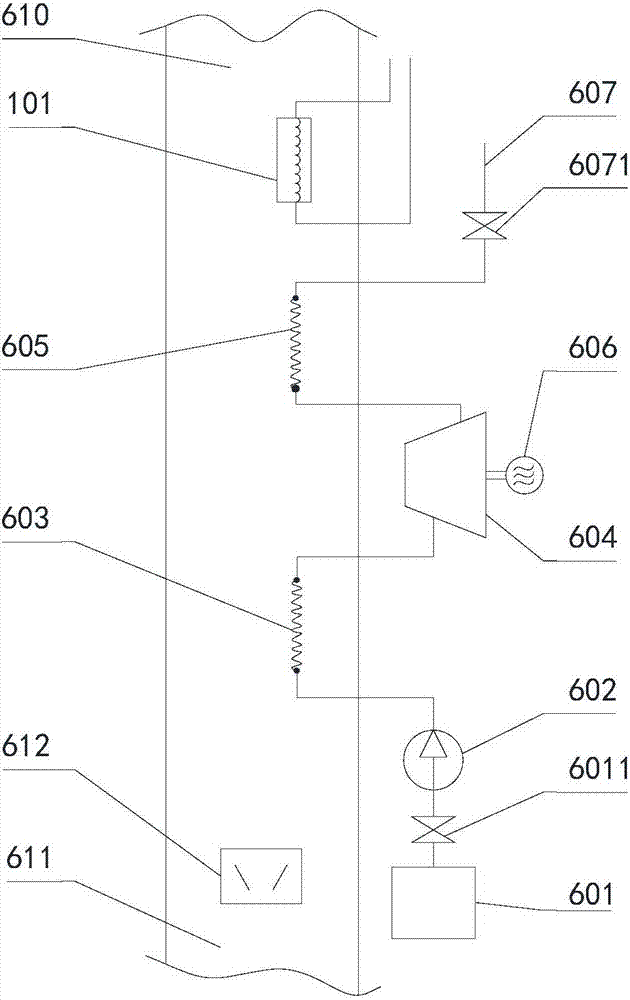
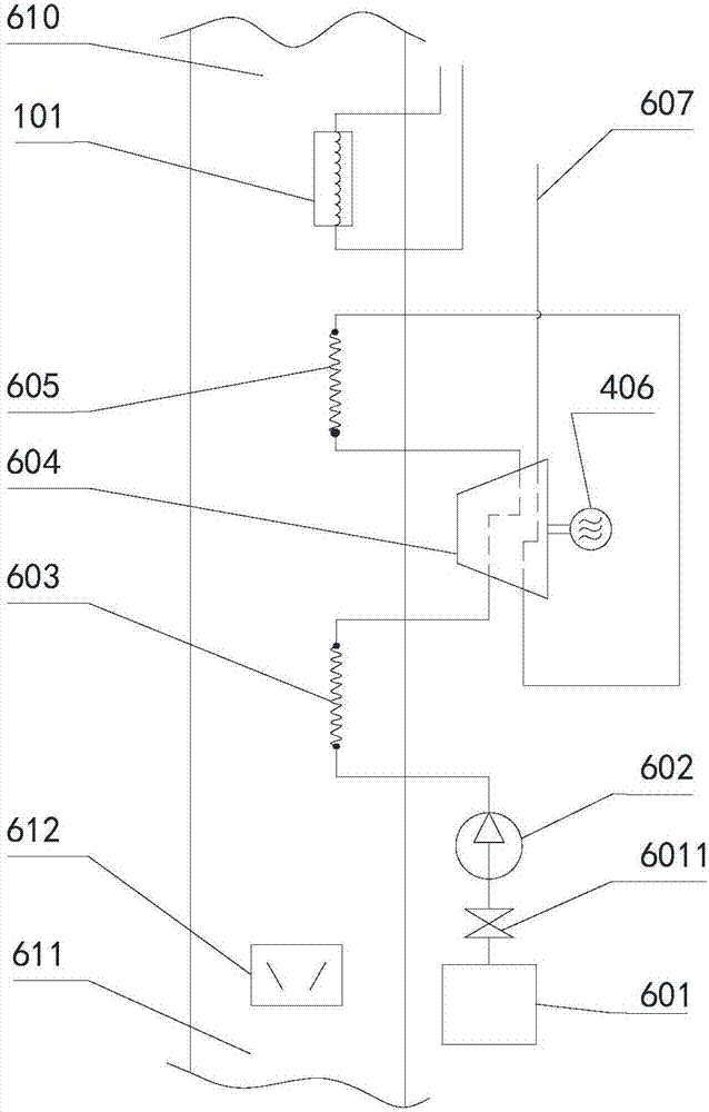
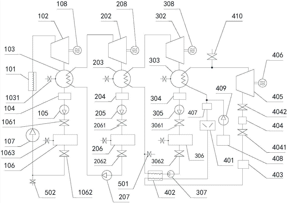
[0061] see Figure 1-Figure 5 As shown, the present embodiment provides a thermal energy utilization system; figure 1 , figure 2 Two schematic flow charts of the thermal energy utilization system provided in this embodiment; Figure 3-Figure 5 It is the first schematic flow diagram to the third schematic flow diagram of the deep heat energy utilization pipeline in this embodiment; figure 1 , figure 2 The deep heat utilization pipeline connected to the third heat exchange device 101 is not shown.

[0062] see figure 1 , figure 2 As shown, the thermal energy utilization system provided in this embodiment includes a cooling utilization pipeline and a heat source pipeline; the heat source pipeline includes a heat source pipeline inlet 610, a first heat exchange device 603, and a heat source pipeline outlet 611 in turn; optionally, the heat source pipeline The heat source pipeline inlet 610 of the road is connected to the boiler flue, seawater, air or condenser; preferably...


PUM


Abstract

The invention relates to the technical field of heat energy recycling and reutilization and particularly relates to a heat energy utilizing system and a power station. The heat energy utilizing system comprises a cooling use pipeline and a heat source pipeline, wherein the heat source pipeline sequentially comprises a heat source pipeline inlet, a first heat exchange device and a heat source pipeline outlet; the cooling use pipeline comprises a storage device of a low-temperature working medium for cooling use, the first heat exchange device and a cooling use output opening, which sequentially communicate with each other; and the first heat exchange device is used for utilizing a medium for cooling use in the storage device of the low-temperature working medium for cooling use to cool a hot source medium flowing across the heat source pipeline, delivering the hot source medium to the cooling use output opening and outputting the hot source medium from the cooling use output opening. The invention aims at providing the heat energy utilizing system and the power station and solving the technical problem that a large quantity of heat in boiler smoke pipelines, such as the heat source pipeline, is wasted in the prior art.

Description

technical field [0001] The invention relates to the technical field of heat energy recovery and utilization, in particular to a heat energy utilization system and a power station. Background technique [0002] Chimneys are one of the oldest and most important anti-pollution devices. At the same time, the chimney is also a building facility used in conjunction with the boiler unit in the thermal power plant. Its main function is to lead the soot and harmful gases in the large amount of flue gas discharged by the boiler to high altitudes, increase the diffusion radius, and avoid excessive local pollution; not only In this way, the towering chimneys are also the landmark buildings of thermal power plants. [0003] In the prior art, a chimney is usually used to directly discharge the flue gas in the boiler flue to the atmosphere, which wastes a large amount of heat energy of the flue gas in the boiler flue. Contents of the invention [0004] The purpose of the present invent...

Claims


Application Information

Patent Timeline
IPC IPC(8): F01K27/02F01K7/02
CPCF01K7/02F01K27/02
Inventor 翁志远
Owner 翁志远
Features
  • R&D
  • Intellectual Property
  • Life Sciences
  • Materials
  • Tech Scout
  • Unparalleled Data Quality
  • Higher Quality Content
  • 60% Fewer Hallucinations
Learn More