
Clutch hydraulic oil circuit structure, clutch structure, driving device and method

A technology of hydraulic oil circuit and clutch, applied in the direction of clutch, transmission device, gear transmission device, etc., can solve the problems of increasing the use and maintenance cost of the rack car, reducing the service life of the bearing bush and ring parts, and the damage of the bearing bush and ring parts. , to achieve the effect of reducing maintenance costs, low costs, and ensuring smooth switching

Active Publication Date: 2019-11-12
ZHUZHOU ELECTRIC LOCOMOTIVE CO LTD
View PDF6 Cites 0 Cited by
  • Summary
  • Abstract
  • Description
  • Claims
  • Application Information

AI Technical Summary

Problems solved by technology

However, this clutch action mode will damage the bearing bush and ring parts, reduce the service life of the bearing bush and ring parts, and increase the use and maintenance cost of the rack car

Method used


Image

  • Clutch hydraulic oil circuit structure, clutch structure, driving device and method
  • Clutch hydraulic oil circuit structure, clutch structure, driving device and method
  • Clutch hydraulic oil circuit structure, clutch structure, driving device and method

Examples


Embodiment Construction

[0023] The "upper end" and "top end" in the present invention refer to the end close to the shell; "lower end" and "bottom end" are vice versa.

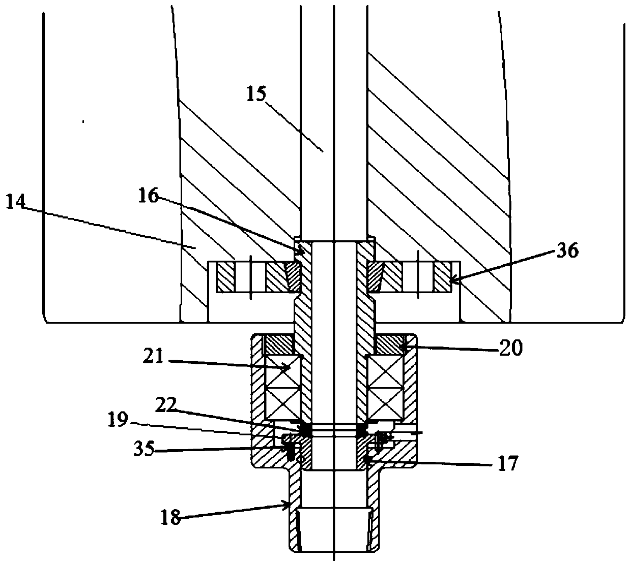
[0024] like figure 1 As shown, the hydraulic oil circuit structure includes an oil channel 15 arranged in the axle 14; one end of a first inner tube 16 communicating with the inlet end of the oil channel 15 is installed on the axle 14 with an interference fit, and can be The axle 14 rotates; the other end of the inner tube 16 communicates with the second inner tube 17 ; the second inner tube 17 is fixedly connected to the inner wall of the nozzle nozzle 18 .

[0025] The bottom end of the second inner tube 17 is pressed into the oil nozzle nozzle 18 with an interference fit; the top side wall of the second inner tube 17 is provided with a protrusion 19; Elastic connection.

[0026] The inner diameter of the upper end of the oil nozzle nozzle 18 is larger than the inner diameter of the lower end of the oil nozzle nozzle 18; There i...


PUM


Abstract

The invention discloses a clutch hydraulic oil way structure, a clutch structure, a driving device and a method. The hydraulic oil way structure comprises an oil way channel formed in a vehicle axle; one end of a first inner pipe for communicating with an inlet end of the oil way channel is mounted on the axle in an interference fit manner, and can rotate along with the vehicle axle; the other end of the inner pipe communicates with a second inner pipe; and the second inner pipe is fixedly connected with the inner wall of an oil nozzle. The hydraulic oil way structure realizes reliable injection of hydraulic oil in movement of a toothed rail vehicle, and realizes looseness of a clutch to realize switching of power conduction modes to guarantee smooth power switching of the toothed rail vehicle; the clutch structure is safe and reliable, and is low in cost; the toothed rail driving and the wheel rail driving can be realized through system switching; and the synthesis of the toothed rail driving and the wheel rail driving in one set of systems is realized.

Description

technical field [0001] The invention relates to the field of rail locomotives, in particular to a clutch hydraulic oil circuit structure, a clutch structure, a driving device and a method. Background technique [0002] At present, domestic rack cars are in their infancy, and how to realize the integration of rack drive and wheel-rail drive at the same time is a difficult point. The rack car driving scheme that has been proposed so far is not completely safe and reliable in terms of the principle of clutch action. It mainly presses the gear to the left through the clutch, and crushes the bearing bush and the ring parts that are interference-connected with the axle to achieve the ring The purpose of consolidating such parts and bearing bushes, gears and clutches into one, so as to realize the purpose of gears driving axles. However, this clutch action mode will damage the bearing bush and ring parts, reduce the service life of the bearing bush and ring parts, and increase the...

Claims


Application Information

Patent Timeline
Patent Type & Authority Patents(China)
IPC IPC(8): F16D25/12F16D25/0638F16H3/093
CPCF16D25/0638F16D25/14F16H3/093
Inventor 魏宏图廖志伟易兴利谢加辉邹文辉吕爱萍杜银兵王艳芝陈国胜高彬祝贺张又孔张冲何烨陈宇向
Owner ZHUZHOU ELECTRIC LOCOMOTIVE CO LTD
Learn More