A variable displacement rotor pump

A rotor pump and displacement technology, which is applied in the direction of rotary piston pumps, pumps, lubricating pumps, etc., can solve the problems of viscosity drop, affecting the oil lubrication effect, safe operation of the engine, and rising lubricating oil temperature, so as to achieve low power consumption and torque. The effect of variable flexibility and strong anti-interference

Active Publication Date: 2022-05-24
HUNAN OIL PUMP
View PDF5 Cites 0 Cited by
  • Summary
  • Abstract
  • Description
  • Claims
  • Application Information

AI Technical Summary

Problems solved by technology

The continuous increase of oil pressure will cause the temperature of lubricating oil to rise and the viscosity to drop, which will affect the lubricating effect of the oil and the safe operation of the engine.

Method used


Image

  • A variable displacement rotor pump
  • A variable displacement rotor pump
  • A variable displacement rotor pump

Examples


Embodiment Construction

[0026] In order to facilitate the understanding of those skilled in the art, the present invention will be further described below with reference to the embodiments and the accompanying drawings, and the contents mentioned in the embodiments are not intended to limit the present invention.

[0027] In the description of the present invention, it should be understood that the terms "center", "longitudinal", "lateral", "length", "width", "thickness", "upper", "lower", "front", " Rear, Left, Right, Vertical, Horizontal, Top, Bottom, Inner, Outer, Clockwise, Counterclockwise, etc. The positional relationship is based on the orientation or positional relationship shown in the accompanying drawings, which is only for the convenience of describing the present invention and simplifying the description, rather than indicating or implying that the referred device or element must have a specific orientation, be constructed and operated in a specific orientation, Therefore, it should not ...


PUM


Abstract

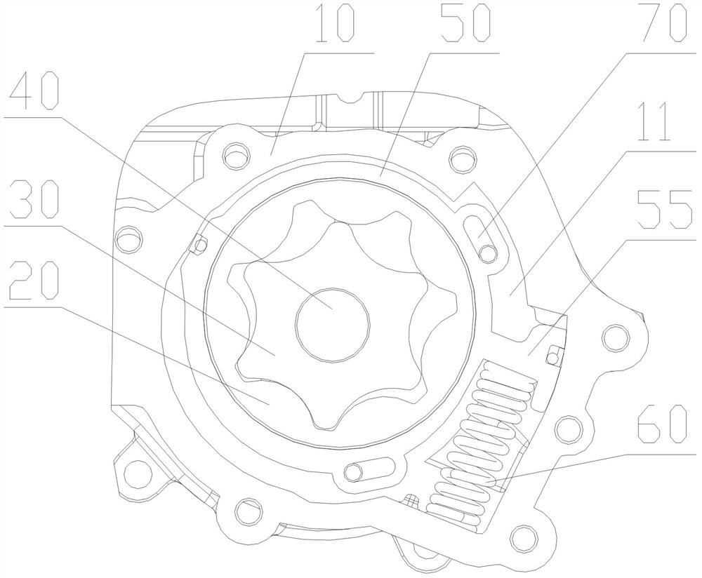
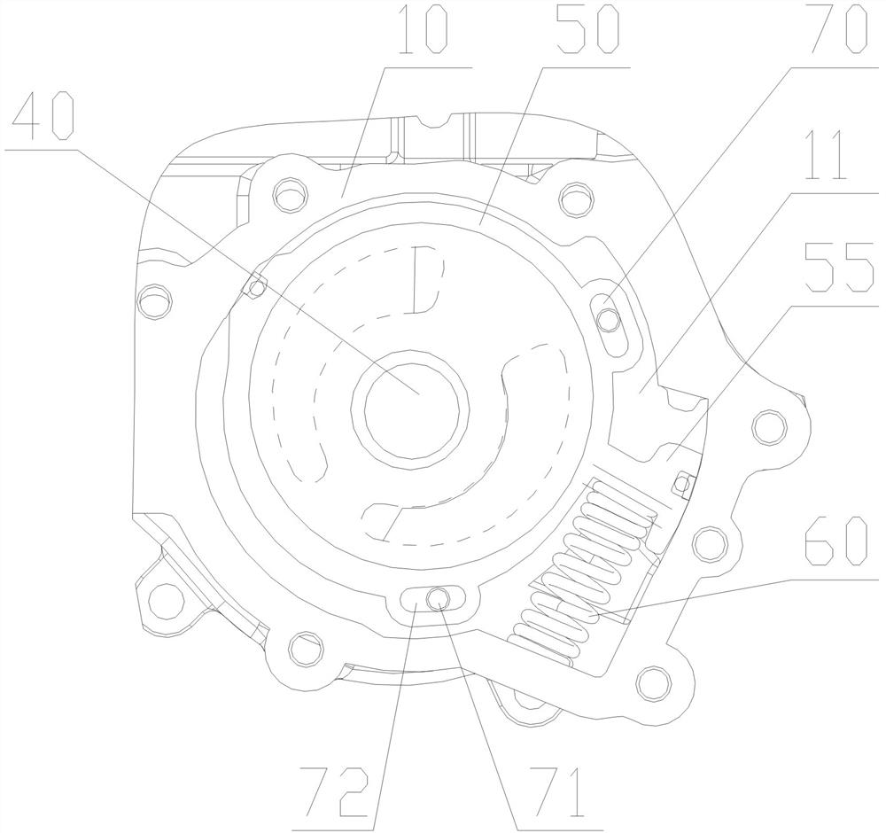
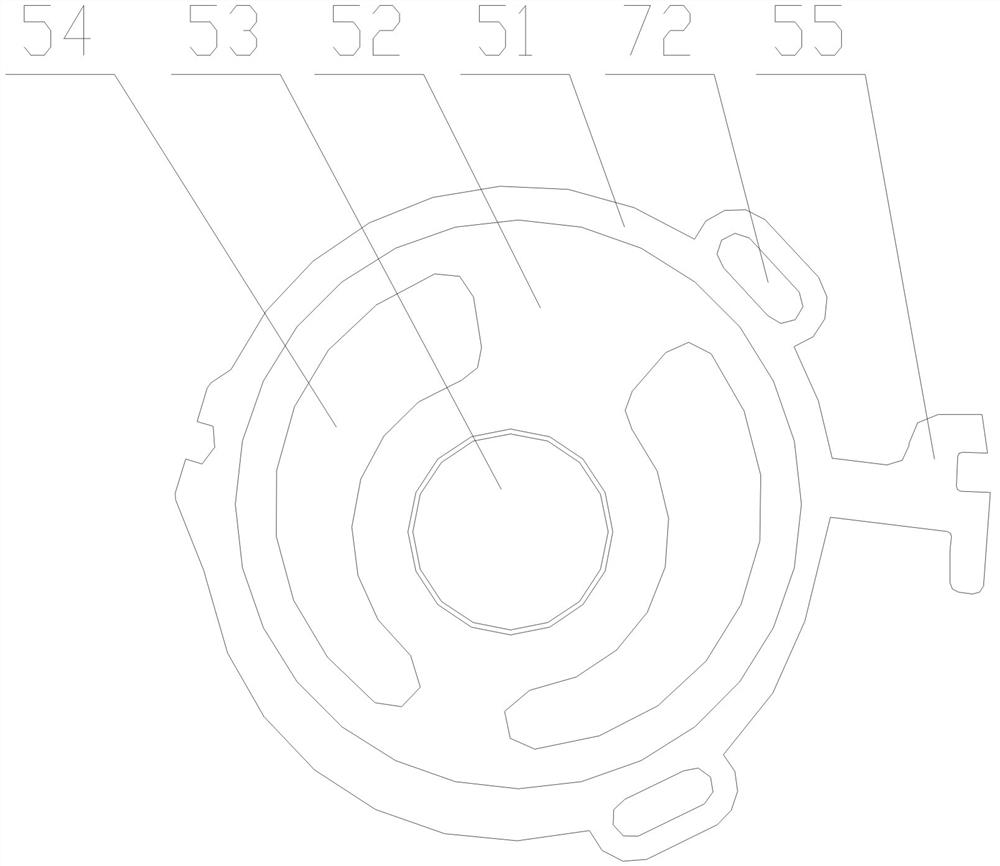
The invention provides a variable displacement rotor pump, which includes a pump body, an outer rotor, an inner rotor, and a drive shaft. The pump body is provided with a shaft hole and a cavity, and the bottom wall of the cavity is provided with an oil inlet cavity and oil outlet cavity, the cavity of the pump body is equipped with an inner casing and a variable spring, the inner casing is composed of a ring-shaped wall plate and a bottom plate, and the bottom plate is provided with an eccentric circular hole and two two arc-shaped through holes, the positions of the two arc-shaped through holes correspond to the oil inlet chamber and the oil outlet chamber respectively; the hollow part in the middle of the inner housing is the rotor chamber, and the outer rotor and inner rotor are installed in the rotor chamber Inside; the wall plate of the inner casing is provided with an outwardly protruding spring pressing block, one side of the spring pressing block is in contact with the variable spring, and the other side is in contact with the cavity side wall of the pump body A variable control cavity is formed between them; at least two sets of movement limit mechanisms are arranged between the inner casing and the pump body, and the movement limit mechanism can control the rotation range of the inner casing in the cavity of the pump body. Limit.

Description

technical field [0001] The invention relates to an engine lubricating system, in particular to a variable displacement rotor type oil pump. Background technique [0002] The rotor type oil pump is mainly composed of inner and outer rotors, oil pump body and oil pump cover and other parts. The active inner rotor and the driven outer rotor are installed in the rotor cavity of the pump body. The inner rotor is fixed on the driving shaft, the outer rotor can rotate freely in the rotor cavity, there is a certain eccentric distance between the two, and the inner rotor drives the outer rotor to rotate together in the same direction. [0003] Generally, the inner rotor of the rotary oil pump has 4 or more convex teeth, and the number of concave teeth of the outer rotor is one more than that of the inner rotor, so that the inner and outer rotors can rotate in the same direction and asynchronously. The outline shape curve is a trochoid. The tooth profile of the rotor is designed so...

Claims


Application Information

Patent Timeline
Patent Type & Authority Patents(China)
IPC IPC(8): F16N13/20F04C2/10
CPCF04C2/10F16N13/20
Inventor 许仲秋刘铁飞
Owner HUNAN OIL PUMP
Why Eureka
Try Eureka